Netgear FE508 Installation Guide - Page 26
Connecting Devices to the Switch, Connecting, vices to the Switch, Appendix, Cabling Guidelines
 |
UPC - 606449000146
View all Netgear FE508 manuals
Add to My Manuals
Save this manual to your list of manuals |
Page 26 highlights
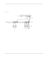
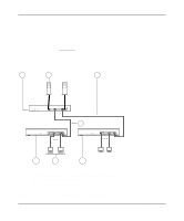
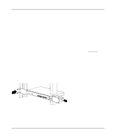
Installation Guide for the Model FS508 Fast Ethernet Switch 5. Insert two pan-head screws with nylon washers through each bracket and into the rack. 6. Using a #2 Phillips screwdriver, tighten the screws to secure the switch to the rack. 7. Install any additional devices in your stack. For proper ventilation, make sure that the switch has at least 2 inches of space on each side and 5 inches of space at the back. It is very important that the fans located in the rear panel are not blocked. Restricted airflow could cause overheating of the components. For instructions on connecting to additional switches or other devices, refer to "Connecting Devices to the Switch." Connecting Devices to the Switch To connect devices to the switch, follow these steps: 1. Connect to another device through any of the ports on the switch. The Normal/Uplink push button eliminates the need to use a crossover twisted pair cable when connecting similarly wired devices. If you are connecting through port 8, set the Normal/ Uplink push button using the following guidelines to configure port 8: • Set the Normal/Uplink push button to the Normal position and use a straight-through twisted pair cable if the remote end of the cable is connected to an MDI wired device such as a PC, a server, or a router. • Set the Normal/Uplink push button to the Uplink position and use a straight-through twisted pair cable if the remote end of the cable is connected to an MDI-X wired device such as a 10 Mbps or 100 Mbps hub or repeater, or for backbone connection to another switch. The UTP ports without the Normal/Uplink push button are by default normal ports and cannot be configured for uplink wiring. If you are using one of the ports without the Normal/Uplink push button to connect to another normal port as on a hub or repeater, a crossover twisted pair cable must be used to connect the two ports. For further cabling guidelines, refer to Appendix C, "Cabling Guidelines." 4-4 Installation
-
 1
1 -
2
-
3
-
4
-
5
-
6
-
7
-
8
-
9
-
10
-
11
-
12
-
13
-
14
-
15
-
16
-
17
-
18
-
19
-
20
-
 21
21 -
 22
22 -
 23
23 -
 24
24 -
 25
25 -
 26
26 -
 27
27 -
 28
28 -
 29
29 -
 30
30 -
 31
31 -
32
-
33
-
34
-
35
-
36
-
37
-
38
-
39
-
40
-
41
-
42
 |
 |
