Netgear FE508 Installation Guide - Page 36
Table B-1 lists the pin assignments for the RJ-45 plug and the vista RJ-45 connector.
 |
UPC - 606449000146
View all Netgear FE508 manuals
Add to My Manuals
Save this manual to your list of manuals |
Page 36 highlights
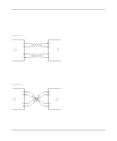
Installation Guide for the Model FS508 Fast Ethernet Switch Table B-1 lists the pin assignments for the RJ-45 plug and the vista RJ-45 connector. Table 5-1. Pin 1 2 3 6 4, 5, 7, 8 RJ-45 plug and vista RJ-45 connector pin assignments Normal assignment Uplink assignment Input Receive Data + Output Transmit Data + Input Receive Data - Output Transmit Data - Output Transmit Data + Input Receive Data + Output Transmit Data - Input Receive Data - Internal termination, not used for data transmission B-2 Connector Pin Assignments
-
 1
1 -
2
-
3
-
4
-
5
-
6
-
7
-
8
-
9
-
10
-
11
-
12
-
13
-
14
-
15
-
16
-
17
-
18
-
19
-
20
-
21
-
22
-
23
-
24
-
25
-
26
-
27
-
28
-
29
-
30
-
 31
31 -
 32
32 -
 33
33 -
 34
34 -
 35
35 -
 36
36 -
 37
37 -
 38
38 -
 39
39 -
 40
40 -
 41
41 -
42
 |
 |

Installation Guide for the Model FS508 Fast Ethernet Switch
B-2
Connector Pin Assignments
Table B-1 lists the pin assignments for the RJ-45 plug and the vista RJ-45 connector.
Table 5-1.
RJ-45 plug and vista RJ-45 connector
pin assignments
Pin
Normal assignment
Uplink assignment
1
Input Receive Data +
Output Transmit Data +
2
Input Receive Data –
Output Transmit Data –
3
Output Transmit Data +
Input Receive Data +
6
Output Transmit Data –
Input Receive Data –
4, 5, 7, 8
Internal termination, not used for data transmission