Netgear FE508 Installation Guide - Page 14
Fast Ethernet Ports, Normal/Uplink Push Button
 |
UPC - 606449000146
View all Netgear FE508 manuals
Add to My Manuals
Save this manual to your list of manuals |
Page 14 highlights
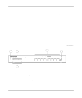
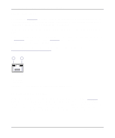
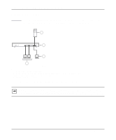
Installation Guide for the Model FS508 Fast Ethernet Switch Fast Ethernet Ports As illustrated in Figure 2-1, the Model FS508 switch is equipped with eight autosensing 10/100 Mbps Fast Ethernet ports. The network access speed for the 10/100 Mbps ports is automatically sensed and displayed on the front panel by the 100 Mbps LEDs. The 10/100 Mbps ports support only unshielded twisted pair (UTP) cable using an 8-pin RJ-45 plug. Each of the 10/100 Mbps ports uses vista RJ-45 connectors that have built-in LEDs, as illustrated in Figure 2-2. The LEDs, as described in Table 2-1, indicate that the connection to the port is valid and that the port is operating in full-duplex mode. For further information about the vista RJ-45 connector and the RJ-45 connector, refer to Appendix B, "Connector Pin Assignments." 1 2 735EA Key: 1 = Link LED 2 = FDX LED Figure 2-2. The vista RJ-45 connector with built-in LEDs Normal/Uplink Push Button The Normal/Uplink push button on the front panel of the switch, as illustrated in Figure 2-1, allows you to select uplink (MDI) or normal (MDI-X) wiring for port 1 on the Model FS508 switch. This port is configured for normal wiring to connect to a PC when the push button is in the out position. When the push button is pressed in, this port is configured for uplink wiring to connect to another switch or to a hub, using a straight-through twisted pair cable. 2-2 Physical Description
-
 1
1 -
2
-
3
-
4
-
5
-
6
-
7
-
8
-
 9
9 -
 10
10 -
 11
11 -
 12
12 -
 13
13 -
 14
14 -
 15
15 -
 16
16 -
 17
17 -
 18
18 -
 19
19 -
20
-
21
-
22
-
23
-
24
-
25
-
26
-
27
-
28
-
29
-
30
-
31
-
32
-
33
-
34
-
35
-
36
-
37
-
38
-
39
-
40
-
41
-
42
 |
 |
