Netgear GSM7224v1 GSM7212 Hardware manual
Netgear GSM7224v1 - Layer 2 Managed Gigabit Switch Manual
 |
View all Netgear GSM7224v1 manuals
Add to My Manuals
Save this manual to your list of manuals |
Netgear GSM7224v1 manual content summary:
- Netgear GSM7224v1 | GSM7212 Hardware manual - Page 1
Managed Layer 2 Switches GSM7212, GSM7224, and GSM7248 Hardware Installation Guide NETGEAR, Inc. 4500 Great America Parkway Santa Clara, CA 95054 USA 201-10814-01 March 2006 - Netgear GSM7224v1 | GSM7212 Hardware manual - Page 2
accordance with the regulations may, however, be subject to certain restrictions. Please refer to the notes in the operating instructions. t is hereby certified that the NETGEAR ProSafe™ 24-Port Gigabit L2 Managed Switch Model GSM7224 has been suppressed in accordance with the conditions set out in - Netgear GSM7224v1 | GSM7212 Hardware manual - Page 3
and used in accordance with the instructions, may cause harmful interference to du Canada. Cet appareil numérique (NETGEAR ProSafe™ 24-Port Gigabit L2 Managed Switch Model Support Refer to the Support Information Card that shipped with your Managed Layer 2 Fast Ethernet Switch. World Wide Web NETGEAR - Netgear GSM7224v1 | GSM7212 Hardware manual - Page 4
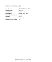
Product and Publication Details Model Number: Publication Date: Product Family: Product Name: Home or Business Product: Language: Publication Part Number: Publication Version Number GSM7212, GSM7224, GSM7248 March 2006 managed switch Managed Layer 2 Switch Business English 201-10814-01 1.0 - Netgear GSM7224v1 | GSM7212 Hardware manual - Page 5
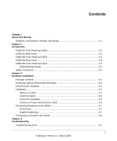
About This Manual Audience, Conventions, Formats, and Scope 1-1 Chapter 2 Introduction GSM7212 Front Panel and LEDs 2-1 GSM7212 Rear Panel ...2-2 GSM7224 Front Panel and LEDs 2-3 GSM7224 Rear Panel ...2-4 GSM7248 Front Panel and LEDs 2-4 GSM7248 Rear Panel 2-5 Safety Instructions ...2-5 Chapter - Netgear GSM7224v1 | GSM7212 Hardware manual - Page 6
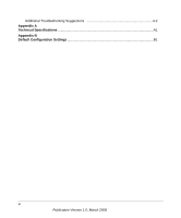
Additional Troubleshooting Suggestions 4-2 Appendix A Technical Specifications ...A1 Appendix B Default Configuration Settings B1 vi Publication Version 1.0, March 2006 - Netgear GSM7224v1 | GSM7212 Hardware manual - Page 7
Manual The Managed Layer 2 Switches GSM7212, GSM7224, and GSM7248 Hardware Installation Guide contains information for hardware installation of the NETGEAR® GSM7212, GSM7224, and GSM7248 switches. Audience, Conventions, Formats, and Scope This guide , commands, IP addresses This guide uses the - Netgear GSM7224v1 | GSM7212 Hardware manual - Page 8
Scope Product version Manual publication date • ProSafe 12-Port Gigabit L2 Managed Switch Model GSM7212 • ProSafe 24-Port Gigabit L2 Managed Switch Model GSM7224 • ProSafe 48-Port Gigabit L2 Managed Switch Model GSM7248 March 2006 Note: Product updates are available on the NETGEAR, Inc. Web site - Netgear GSM7224v1 | GSM7212 Hardware manual - Page 9
bottlenecks, boost performance, and increase productivity. This guide describes the hardware for the following NETGEAR switches: • ProSafe 12-Port Gigabit L2 Managed Switch Model GSM7212 • ProSafe 24-Port Gigabit L2 Managed Switch Model GSM7224 • ProSafe 48-Port Gigabit L2 Managed Switch Model - Netgear GSM7224v1 | GSM7212 Hardware manual - Page 10
Managed Layer 2 Switches GSM7212, GSM7224, and GSM7248 Hardware Installation Guide The following table describes the LEDs on the front panel of the switch. Table 2-1. LED Descriptions for GSM7212 LED Description Power Mode MaxSpd (maximum speed), - Netgear GSM7224v1 | GSM7212 Hardware manual - Page 11
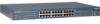
Managed Layer 2 Switches GSM7212, GSM7224, and GSM7248 Hardware Installation Guide GSM7224 Front Panel and LEDs The following figure shows the front panel of the GSM7224. The front panel contains LEDs, RJ-45 jacks, and SFP - Netgear GSM7224v1 | GSM7212 Hardware manual - Page 12
Managed Layer 2 Switches GSM7212, GSM7224, and GSM7248 Hardware Installation Guide GSM7224 Rear Panel The rear panel has a standard AC power receptacle for the supplied power cord. Power receptacle Figure 2-4 GSM7248 Front Panel and LEDs The - Netgear GSM7224v1 | GSM7212 Hardware manual - Page 13
GSM7224, and GSM7248 Hardware Installation Guide Table 2-3. GSM7248 LED Description the supplied power cord. Power Figure 2-6 Safety Instructions Use the following safety guidelines to ensure your precautions. • Observe and follow service markings. - Do not service any product except as explained - Netgear GSM7224v1 | GSM7212 Hardware manual - Page 14
system components, and never operate the product in a wet environment. If the system gets wet, see the appropriate section in your troubleshooting guide or contact your trained service provider. • Do not push any objects into the openings of your system. Doing so can cause fire or electric shock by - Netgear GSM7224v1 | GSM7212 Hardware manual - Page 15
Layer 2 Switches GSM7212, GSM7224, and GSM7248 Hardware Installation Guide • Use only approved power cables. If you have power cables are equipped with 3-prong plugs to help ensure proper grounding. Do not use adapter plugs or remove the grounding prong from a cable. If you must use an extension - Netgear GSM7224v1 | GSM7212 Hardware manual - Page 16
Managed Layer 2 Switches GSM7212, GSM7224, and GSM7248 Hardware Installation Guide 2-8 Introduction v1.0, March 2006 - Netgear GSM7224v1 | GSM7212 Hardware manual - Page 17
the Command Line Interface Reference for the ProSafe 7200 Series Layer-2 Switches, the Administration Manual for the 7200 Series Layer-2 Switches, the Quick Install Guide, and this Hardware Installation Guide • Warranty and Support Card • Quick Install Guide If you ordered SFP modules with your - Netgear GSM7224v1 | GSM7212 Hardware manual - Page 18
Managed Layer 2 Switches GSM7212, GSM7224, and GSM7248 Hardware Installation Guide Protecting Against Electrostatic Discharge Warning: Static electricity can harm delicate components inside your system. To prevent static damage, discharge static electricity from your body before - Netgear GSM7224v1 | GSM7212 Hardware manual - Page 19
Managed Layer 2 Switches GSM7212, GSM7224, and GSM7248 Hardware Installation Guide 4. Make sure that all items are present. See "Package Contents" on page 3-1. Note: If any item is found missing or damaged, contact your local NETGEAR reseller for replacement. 5. Inspect the products and accessories - Netgear GSM7224v1 | GSM7212 Hardware manual - Page 20
Managed Layer 2 Switches GSM7212, GSM7224, and GSM7248 Hardware Installation Guide Table 3-1. Site Requirements for Switch Location (continued) (continued) Requirements Access Power source Environment Temperature Operating humidity Ventilation Cabling Locate the switch in a position that lets - Netgear GSM7224v1 | GSM7212 Hardware manual - Page 21
Managed Layer 2 Switches GSM7212, GSM7224, and GSM7248 Hardware Installation Guide Install the Switch You can install the switch on a flat surface or in a standard 19-inch rack. Installing the Switch on a Flat Surface The switch - Netgear GSM7224v1 | GSM7212 Hardware manual - Page 22
GSM7224, and GSM7248 Hardware Installation Guide 4. Align the bracket and these steps to apply AC power. 1. Connect one end of the AC power adapter cable to the rear of the switch, and the other end to a troubleshooting, see Chapter 4, "Troubleshooting". 3-6 Hardware Installation v1.0, March 2006 - Netgear GSM7224v1 | GSM7212 Hardware manual - Page 23
Managed Layer 2 Switches GSM7212, GSM7224, and GSM7248 Hardware Installation Guide Connecting Equipment to the Switch You can connect devices, an SPF Gigabit Ethernet module, and a console to the switch. RJ-45 Ports The switch uses - Netgear GSM7224v1 | GSM7212 Hardware manual - Page 24
GSM7212, GSM7224, and GSM7248 Hardware Installation Guide Connecting a Console to the Switch After you install the switch and apply power, you can connect to it with a terminal or workstation. You can use the Command Line Interface (CLI) to identify the IP address. To use a console, you need the - Netgear GSM7224v1 | GSM7212 Hardware manual - Page 25
following documents are provided for this purpose: • Quick Install Guide: Explains basic setup and configuration (provided as both a print document and in PDF format on the NETGEAR CD). • Command Line Interface Reference for the ProSafe 7200 Series Layer-2 Switches: Gives detailed examples of how - Netgear GSM7224v1 | GSM7212 Hardware manual - Page 26
Managed Layer 2 Switches GSM7212, GSM7224, and GSM7248 Hardware Installation Guide 3-10 v1.0, March 2006 Hardware Installation - Netgear GSM7224v1 | GSM7212 Hardware manual - Page 27
lists symptoms, causes, and solutions of possible problems. Table 4-1. Troubleshooting Problem Power LED is off. Link LED is off Ethernet specifications. See Appendix A, "Technical Specifications". Check for a defective adapter card, cable, or port by testing it in an alternate environment where - Netgear GSM7224v1 | GSM7212 Hardware manual - Page 28
4-1 do not resolve your problem, refer to the troubleshooting suggestions in this section. Network Adapter Cards Make sure that the network adapter cards installed in the PCs are in working condition and the software driver has been installed. Configuration If problems occur after you change the - Netgear GSM7224v1 | GSM7212 Hardware manual - Page 29
not support auto-negotiation, the switch only determines the speed correctly and the duplex mode defaults to half-duplex. The gigabit port on the gigabit module negotiates speed, duplex mode, and flow control, provided that the attached device supports auto-negotiation. Troubleshooting 4-3 v1 - Netgear GSM7224v1 | GSM7212 Hardware manual - Page 30
Managed Layer 2 Switches GSM7212, GSM7224, and GSM7248 Hardware Installation Guide 4-4 Troubleshooting v1.0, March 2006 - Netgear GSM7224v1 | GSM7212 Hardware manual - Page 31
media access control 4,000 media access control 16,000 media access size (MAC) addresses per (MAC) addresses per control (MAC) addresses system system per system Addressing Addressing: 48-bit MAC address 10/100/1000 buffer memory 2-MB embedded memory 2-MB embedded memory 12-MB embedded - Netgear GSM7224v1 | GSM7212 Hardware manual - Page 32
GSM7248 Hardware Installation Guide Table A-1. Technical 81 kg) • 802.1Q Static VLAN (up to 4k) • 802.1p Class of Service (CoS) • 802.1D Spanning Tree Protocol (STP) • 802.1w Rapid Spanning Tree Aggregation (LACP) • IGMP v1, v2 snooping support • Port mirroring support • SNMP v3 • RFC1757 • RMON 1 - Netgear GSM7224v1 | GSM7212 Hardware manual - Page 33
Managed Layer 2 Switches GSM7212, GSM7224, and GSM7248 Hardware Installation Guide Table A-1. Technical Specifications (continued) Feature Electromagnetic emissions and immunity Safety GSM7212 GSM7224 • CE mark, commercial • FCC Part 15 Class A VCCI • Class A EN 55022 (CISPR 22) • - Netgear GSM7224v1 | GSM7212 Hardware manual - Page 34
Managed Layer 2 Switches GSM7212, GSM7224, and GSM7248 Hardware Installation Guide A-4 Technical Specifications v1.0, March 2006 - Netgear GSM7224v1 | GSM7212 Hardware manual - Page 35
provides the default settings for the NETGEAR Model GSM7212, GSM7224, and GSM7248 -negotiation Gigabit port type Auto-detect IP configuration DHCP Password protection Disabled User Tree Protocol Enabled (IEEE 802.1s) MAC address aging 300 seconds SNMP community Public: Read-only access - Netgear GSM7224v1 | GSM7212 Hardware manual - Page 36
Managed Layer 2 Switches GSM7212, GSM7224, and GSM7248 Hardware Installation Guide B-2 Default Configuration Settings v1.0, March 2006 - Netgear GSM7224v1 | GSM7212 Hardware manual - Page 37
- Netgear GSM7224v1 | GSM7212 Hardware manual - Page 38
NETGEAR, Inc. 4500 Great America Parkway Santa Clara, CA 95054 USA March 2006
-
 1
1 -
 2
2 -
 3
3 -
 4
4 -
 5
5 -
 6
6 -
 7
7 -
8
-
9
-
10
-
11
-
12
-
13
-
14
-
15
-
16
-
17
-
18
-
19
-
20
-
21
-
22
-
23
-
24
-
25
-
26
-
27
-
28
-
29
-
30
-
31
-
32
-
33
-
34
-
35
-
36
-
37
-
38
 |
 |

201-10814-01
March 2006
NETGEAR
, Inc.
4500 Great America Parkway
Santa Clara, CA 95054 USA
Managed Layer 2 Switches
GSM7212, GSM7224, and
GSM7248 Hardware
Installation Guide