Netgear GSM7224v1 GSM7212 Hardware manual - Page 13
GSM7248 Rear Panel, Safety Instructions, Observe and follow service markings.
 |
View all Netgear GSM7224v1 manuals
Add to My Manuals
Save this manual to your list of manuals |
Page 13 highlights
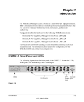
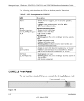
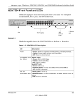
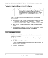
Managed Layer 2 Switches GSM7212, GSM7224, and GSM7248 Hardware Installation Guide Table 2-3. GSM7248 LED Description (continued) 10/100/1000 ports (two LEDs) SFP port (1,000 Mbps only) Speed (left) • Green: Link in 1000 Mbps. • Yellow: Link in 100 Mbps. • Off: Link in 10 Mbps. Link or Activity (right) • Green: Link is up. • Blinking green: The port is sending or receiving packets. • Off: No link is detected. • Solid green: Link is up. • Blinking green: The port is sending or receiving packets in link up status. • Off: No link is detected. GSM7248 Rear Panel The rear panel has a standard AC power receptacle for the supplied power cord. Power Figure 2-6 Safety Instructions Use the following safety guidelines to ensure your own personal safety and to help protect your system from potential damage. To reduce the risk of bodily injury, electrical shock, fire, and damage to the equipment, observe the following precautions. • Observe and follow service markings. - Do not service any product except as explained in your system documentation. - Opening or removing covers that are marked with the triangular symbol with a lightning bolt may expose you to electrical shock. Only a trained service technician should service components inside these compartments. Introduction 2-5 v1.0, March 2006
-
 1
1 -
2
-
3
-
4
-
5
-
6
-
7
-
 8
8 -
 9
9 -
 10
10 -
 11
11 -
 12
12 -
 13
13 -
 14
14 -
 15
15 -
 16
16 -
 17
17 -
 18
18 -
19
-
20
-
21
-
22
-
23
-
24
-
25
-
26
-
27
-
28
-
29
-
30
-
31
-
32
-
33
-
34
-
35
-
36
-
37
-
38
 |
 |