Netgear GSM7224v1 GSM7212 Hardware manual - Page 19
Installation, Select a Location
 |
View all Netgear GSM7224v1 manuals
Add to My Manuals
Save this manual to your list of manuals |
Page 19 highlights
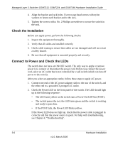
Managed Layer 2 Switches GSM7212, GSM7224, and GSM7248 Hardware Installation Guide 4. Make sure that all items are present. See "Package Contents" on page 3-1. Note: If any item is found missing or damaged, contact your local NETGEAR reseller for replacement. 5. Inspect the products and accessories for damage. Report any damage immediately. Installation Install the equipment in the sequence presented in this chapter: 1. Select a Location. See "Select a Location" on page 3-3. 2. Install the Switch. See "Install the Switch" on page 3-5. 3. Check the installation. See "Check the Installation" on page 3-6 4. Apply power, and check the LEDs. See "Connect to Power and Check the LEDs" on page 3-6. Select a Location The switch can be mounted in a standard 19-inch (48.26-centimeter) rack, wallmounted, or left freestanding (placed on a tabletop). The site where you install the switch can affect its performance. Before installing the switch or switches, make sure that the location meets the following site requirements. Table 3-1. Site Requirements for Switch Location Requirements Mounting • Desktop installations: Provide a flat table or shelf surface. • Rack-mount Iistallations: Use a 19-inch (48.3-centimeter) EIA standard equipment rack that is grounded and physically secure. You need the rack-mount kit supplied with your switch. Hardware Installation 3-3 v1.0, March 2006
-
 1
1 -
2
-
3
-
4
-
5
-
6
-
7
-
8
-
9
-
10
-
11
-
12
-
13
-
 14
14 -
 15
15 -
 16
16 -
 17
17 -
 18
18 -
 19
19 -
 20
20 -
 21
21 -
 22
22 -
 23
23 -
 24
24 -
25
-
26
-
27
-
28
-
29
-
30
-
31
-
32
-
33
-
34
-
35
-
36
-
37
-
38
 |
 |