Netgear GSM7252PS GSM72xxPS and GSM73xxSv2 Series Managed Switch Hardware Inst
Netgear GSM7252PS - ProSafe 52 Ports Gigabit Ethernet L2 Managed Stackable Switch Manual
 |
UPC - 606449071665
View all Netgear GSM7252PS manuals
Add to My Manuals
Save this manual to your list of manuals |
Netgear GSM7252PS manual content summary:
- Netgear GSM7252PS | GSM72xxPS and GSM73xxSv2 Series Managed Switch Hardware Inst - Page 1
Managed Stackable Switches GSM7200PS and GSM7300S Series Hardware Installation Guide 350 East Plumeria Drive San Jose, CA 95134 USA March 2010 202-10532-02 v1.0 - Netgear GSM7252PS | GSM72xxPS and GSM73xxSv2 Series Managed Switch Hardware Inst - Page 2
Managed Stackable Switches GSM7200PS and GSM7300S Series Hardware Installation Guide © 2010 NETGEAR, Inc.© 2010 by NETGEAR, Inc. All rights reserved. No part of this publication may be reproduced, transmitted, transcribed, stored in a retrieval system, or translated into any language in any - Netgear GSM7252PS | GSM72xxPS and GSM73xxSv2 Series Managed Switch Hardware Inst - Page 3
Supply 26 Connecting Equipment to the Switch 26 RJ-45 Ports 26 Connecting a Console to the Switch 26 Chapter 3 Troubleshooting Troubleshooting Chart 29 Additional Troubleshooting Suggestions 30 Appendix A Technical Specifications Specifications for GSM7228PS and GSM7252PS 31 Table of Contents - Netgear GSM7252PS | GSM72xxPS and GSM73xxSv2 Series Managed Switch Hardware Inst - Page 4
Managed Stackable Switches GSM7200PS and GSM7300S Series Hardware Installation Guide Specifications for GSM7328S and GSM7352S 33 Appendix B Default Configuration Settings Appendix C Notification of Compliance 4 | Table of Contents - Netgear GSM7252PS | GSM72xxPS and GSM73xxSv2 Series Managed Switch Hardware Inst - Page 5
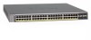
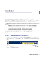
This guide describes hardware installation and basic troubleshooting for the following NETGEAR switches: • ProSafe 24-port Gigabit L2+ Managed Stackable Switch with PoE GSM7228PS • ProSafe 48-port Gigabit L2+ Managed Stackable Switch with PoE GSM7252PS • ProSafe 24-port Gigabit L3 Managed Stackable - Netgear GSM7252PS | GSM72xxPS and GSM73xxSv2 Series Managed Switch Hardware Inst - Page 6
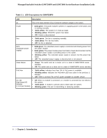
Managed Stackable Switches GSM7200PS and GSM7300S Series Hardware Installation Guide Table 1-1. LED Descriptions for GSM7228PS LED Description ID This is the stack member ID (1-8) that the software assigns to the switch. Power • Solid green: The power module is present, is supplying power to - Netgear GSM7252PS | GSM72xxPS and GSM73xxSv2 Series Managed Switch Hardware Inst - Page 7
Managed Stackable Switches GSM7200PS and GSM7300S Series Hardware Installation Guide Table 1-1. LED Descriptions for GSM7228PS (Continued) LED Description 10/100/1000M Ports (2 LEDs per port) SPD/Link/ACT LED: • Off: No link is established on the port. • Solid green: A valid 1000 Mbps link is - Netgear GSM7252PS | GSM72xxPS and GSM73xxSv2 Series Managed Switch Hardware Inst - Page 8
Replaceable power supply AC Power Connector Figure 1-2 GSM7228PS Rear Panel The module bays support any combination of the following: • ProSafe 10-Gigabit Ethernet XFP Adapter AX741 • SFP+ Adapter AX743 • CX4 Adapter AX744 • ProSafe 24-Gigabit Stackable Module AX742. For more information, see - Netgear GSM7252PS | GSM72xxPS and GSM73xxSv2 Series Managed Switch Hardware Inst - Page 9
Managed Stackable Switches GSM7200PS and GSM7300S Series Hardware Installation Guide Table 1-3. GSM7252PS LED Description LED Description ID This is the stack member ID (1-8) that the software assigns to the switch. Power • Solid green: The power module is present, is supplying power to the - Netgear GSM7252PS | GSM72xxPS and GSM73xxSv2 Series Managed Switch Hardware Inst - Page 10
Replaceable power supply Figure 1-4 GSM7252PS Rear Panel The module bays support any combination of the following: • ProSafe 10-Gigabit Ethernet XFP Adapter (AX741) • SFP+ Adapter AX743 • CX4 Adapter AX744 • ProSafe 24-Gigabit Stackable Module AX742. For more information, see "Adapters and Modules - Netgear GSM7252PS | GSM72xxPS and GSM73xxSv2 Series Managed Switch Hardware Inst - Page 11
Managed Stackable Switches GSM7200PS and GSM7300S Series Hardware Installation Guide GSM7328S Front Panel and LEDs The following figure shows the front panel of the GSM7328S. The front panel contains LEDs, a Reset button, a USB port, RJ-45 jacks, copper/fiber combo ports, and 10G SFP+ ports. LEDs - Netgear GSM7252PS | GSM72xxPS and GSM73xxSv2 Series Managed Switch Hardware Inst - Page 12
Managed Stackable Switches GSM7200PS and GSM7300S Series Hardware Installation Guide Table 1-5. LED Descriptions for GSM7328S (Continued) LED Description 10/100/1000M Ports (2 LEDs per port) Link/ACT LED: • Off: No link is established on the port. • Solid green: A valid link is established on - Netgear GSM7252PS | GSM72xxPS and GSM73xxSv2 Series Managed Switch Hardware Inst - Page 13
Managed Stackable Switches GSM7200PS and GSM7300S Series Hardware Installation Guide • SFP+ Adapter AX743 • CX4 Adapter AX744 • ProSafe 24-Gigabit Stackable contains LEDs, a Reset button, a USB port, RJ-45 jacks, copper/fiber combo ports, and 10G SFP+ ports. LEDs Reset button Figure 1-7 GSM7352S - Netgear GSM7252PS | GSM72xxPS and GSM73xxSv2 Series Managed Switch Hardware Inst - Page 14
Managed Stackable Switches GSM7200PS and GSM7300S Series Hardware Installation Guide Table 1-6. GSM7352S LED Description (Continued) LEDs Description 10/100/1000M Ports (2 LEDs per port) Link/ACT LED: • Off: No link is established on the port. • Solid green: A valid link is established on the - Netgear GSM7252PS | GSM72xxPS and GSM73xxSv2 Series Managed Switch Hardware Inst - Page 15
Managed Stackable Switches GSM7200PS and GSM7300S Series Hardware Installation Guide The module bays support any combination of the following: • ProSafe 10-Gigabit Ethernet XFP Adapter (AX741) • SFP+ Adapter AX743 • CX4 Adapter AX744 • ProSafe 24-Gigabit Stackable Module AX742. For more information, - Netgear GSM7252PS | GSM72xxPS and GSM73xxSv2 Series Managed Switch Hardware Inst - Page 16
Managed Stackable Switches GSM7200PS and GSM7300S Series Hardware Installation Guide • To help avoid damaging your system, be sure that the voltage selection switch Far Eastern countries such as South Korea and Taiwan - 100 V, 50 Hz in eastern Japan and 100 V, 60 Hz in western Japan - 230 V, 50 Hz - Netgear GSM7252PS | GSM72xxPS and GSM73xxSv2 Series Managed Switch Hardware Inst - Page 17
to access them: - ProSafe 7200PS Managed Switch CLI Manual, Version 8.0.2 - NETGEAR 7000 Series Managed Switch Administration Guide - NETGEAR Installation Guide for the 7000 Series Stackable Managed Switch - This Hardware Installation Guide • ProSafe NMS100 Network Management System 30-day trial CD - Netgear GSM7252PS | GSM72xxPS and GSM73xxSv2 Series Managed Switch Hardware Inst - Page 18
Managed Stackable Switches GSM7200PS and GSM7300S Series Hardware Installation Guide and place it on a secure and clean surface. See "Select a Location" on page 2-19. 3. Remove all packing found missing or damaged, contact your local NETGEAR reseller for replacement. 5. Inspect the products - Netgear GSM7252PS | GSM72xxPS and GSM73xxSv2 Series Managed Switch Hardware Inst - Page 19
Managed Stackable Switches GSM7200PS and GSM7300S Series Hardware Installation Guide 1. Select a Location. See "Select a Location" on page 2-19. 2. Install the Switch. See "Install the Switch with your switch. Locate the switch in a position that lets you access the front panel RJ-45 ports, view the - Netgear GSM7252PS | GSM72xxPS and GSM73xxSv2 Series Managed Switch Hardware Inst - Page 20
Managed Stackable Switches GSM7200PS and GSM7300S Series Hardware Installation Guide Install the Switch You can install the switch on a flat surface or in a standard 19-inch rack. Installing the Switch on a Flat Surface The switch ships with four self-adhesive rubber footpads. Stick one rubber - Netgear GSM7252PS | GSM72xxPS and GSM73xxSv2 Series Managed Switch Hardware Inst - Page 21
both, use one 24-Gigabit Stackable Module AX742 per switch, and then use the remaining module bay foran adapter and corresponding module supported by the switch. You can install these adapters (sold separately) in the switches' high-speed module bays: • ProSafe 10-Gigabit Ethernet XFP Adapter Module - Netgear GSM7252PS | GSM72xxPS and GSM73xxSv2 Series Managed Switch Hardware Inst - Page 22
Managed Stackable Switches GSM7200PS and GSM7300S Series Hardware Installation Guide • ProSafe 24-Gigabit stacking module AX742: Figure 2-11 AX742 • ProSafe 10-Gigabit Ethernet SFP+ Adapter Module AX743: Figure 2-12 AX743 • ProSafe 10-Gigabit Ethernet CX4 Adapter AX744: Figure 2-13 AX744 After the - Netgear GSM7252PS | GSM72xxPS and GSM73xxSv2 Series Managed Switch Hardware Inst - Page 23
Managed Stackable Switches GSM7200PS and GSM7300S Series Hardware Installation Guide • SFP module with LC connector, compatible with the IEEE 802.3z 1000Base-X standard. Figure 2-14 SFP Module Installing an Adapter and Module The steps are - Netgear GSM7252PS | GSM72xxPS and GSM73xxSv2 Series Managed Switch Hardware Inst - Page 24
you can use its console to manage all the switches in the stack. Two of the I/O module slots can be used for stacking, while the remaining two I/O module bays can be used for 10-Gigabit Ethernet uplinks. To set up a stack: 1. Install up to two 24-Gigabit Stackable Modules (AX742) into the high-speed - Netgear GSM7252PS | GSM72xxPS and GSM73xxSv2 Series Managed Switch Hardware Inst - Page 25
Managed Stackable Switches GSM7200PS and GSM7300S Series Hardware Installation Guide Power Module Bay The power module bay provides an easy way to replace a failed power module APS525W or APS135W. If the switch needs to continue to operate while you replace the power supply, an appropriate Redundant - Netgear GSM7252PS | GSM72xxPS and GSM73xxSv2 Series Managed Switch Hardware Inst - Page 26
(100 meters). Connecting a Console to the Switch After you install the switch and apply power, you can connect to it with a terminal or workstation. You can use the Command Line Interface (CLI) to identify the IP address. If you are stacking switches, see "Creating a Stack" on page 2-24. 26 - Netgear GSM7252PS | GSM72xxPS and GSM73xxSv2 Series Managed Switch Hardware Inst - Page 27
as both a print document and in PDF format on the Resource CD). • ProSafe 7200PS Managed Switch CLI Manual, Version 8.0.2: Gives detailed examples of how to use the CLI. • NETGEAR 7000 Series Managed Switch Administration Guide: Describes configuration tasks. Chapter 2: Hardware Installation | 27 - Netgear GSM7252PS | GSM72xxPS and GSM73xxSv2 Series Managed Switch Hardware Inst - Page 28
Troubleshooting Chart Problem Cause Solution Power LED is off. No power is received Check the power cord connections for the switch at the switch and the connected device. Make sure that all cables used are correct and comply with Ethernet specifications. Link LED is off or intermittent. Port - Netgear GSM7252PS | GSM72xxPS and GSM73xxSv2 Series Managed Switch Hardware Inst - Page 29
the integrity of the switch by resetting the switch. To reset the switch, use the Tools> Reset command or remove AC power from the switch and then reapply AC power. If the problem continues, contact NETGEAR technical support. Auto-Negotiation: The copper 10/100/1000 Mbps ports negotiate the correct - Netgear GSM7252PS | GSM72xxPS and GSM73xxSv2 Series Managed Switch Hardware Inst - Page 30
management GSM7228PS GSM7252PS • 802.3 10BASE-T • 802.3u 100BASE-TX • 802.3z 1000BASE-SX • 802.3z 1000BASE-LX • 802.3ab 1000BASE-T • 802.3ae 10000BASE-LR • 802.3ae 10000BASE-SR • 802.3af Power over Ethernet • 802.3at Enhanced Power over Ethernet • 802.3x flow control • Port mirroring support - Netgear GSM7252PS | GSM72xxPS and GSM73xxSv2 Series Managed Switch Hardware Inst - Page 31
Managed Stackable Switches GSM7200PS and GSM7300S Series Hardware Installation Guide Table A-1. Technical Specifications for GSM7228PS and GSM7252PS (Continued) Feature GSM7228PS GSM7252PS Layer 2 services • 802.1Q Static VLAN (Up to 4k) • 802.1p Class of Service (CoS) • 802.1D Spanning Tree - Netgear GSM7252PS | GSM72xxPS and GSM73xxSv2 Series Managed Switch Hardware Inst - Page 32
Managed Stackable Switches GSM7200PS and GSM7300S Series Hardware Installation Guide Table A-1. Technical Specifications for GSM7228PS and GSM7252PS (Continued) Feature GSM7228PS GSM7252PS Power consumption 545 W maximum 100-240VAC, 50-60 570 W maximum 100-240VAC, 50-60 Hz universal input - Netgear GSM7252PS | GSM72xxPS and GSM73xxSv2 Series Managed Switch Hardware Inst - Page 33
Managed Stackable Switches GSM7200PS and GSM7300S Series Hardware Installation Guide Table A-2. Specifications for GSM7328S and GSM7352S (Continued) Feature Switch management Layer 2 Services Layer 3 Services GSM7328S GSM7352S • Port mirroring support • SNMP v1, v2c, v3 • RFC1757 RMON 1 groups - Netgear GSM7252PS | GSM72xxPS and GSM73xxSv2 Series Managed Switch Hardware Inst - Page 34
Managed Stackable Switches GSM7200PS and GSM7300S Series Hardware Installation Guide Table A-2. Specifications for GSM7328S and GSM7352S (Continued) Feature GSM7328S GSM7352S Interface (Auto Uplink on all RJ-45 ports) • 24 RJ-45 connectors for 10BASE-T, 100BASE-TX, and 1000BASE-T • Four slots - Netgear GSM7252PS | GSM72xxPS and GSM73xxSv2 Series Managed Switch Hardware Inst - Page 35
storm control Enabled Gigabit port type Auto detect Management IP configuration DHCP Password protection Disabled User name Admin Password (none) Web access Enabled Java mode Enabled VLAN All ports belong to default VLAN (VLAN 1) as untagged ports IP multicast filtering Disabled - Netgear GSM7252PS | GSM72xxPS and GSM73xxSv2 Series Managed Switch Hardware Inst - Page 36
Managed Stackable Switches GSM7200PS and GSM7300S Series Hardware Installation Guide Feature GVRP GMRP IP routing RIP MAC address aging OSPF SNMP community DHCP Server VLAN Ingress filtering IP multicast filtering VRRP IGMP DVMRP PIM-SM PIM-DM IPv6 routing PIM-SM(IPv6) PIM-DM(IPv6) MLD OSPFv3 - Netgear GSM7252PS | GSM72xxPS and GSM73xxSv2 Series Managed Switch Hardware Inst - Page 37
It is hereby certified that the NETGEAR ProSafe 24-port Gigabit L2+ Managed Stackable Switch with PoE GSM7228PS has been suppressed in accordance in the operating instructions. It is hereby certified that the NETGEAR ProSafe 24-port Gigabit L3 Managed Stackable Switch GSM7328S has been suppressed - Netgear GSM7252PS | GSM72xxPS and GSM73xxSv2 Series Managed Switch Hardware Inst - Page 38
sur le brouillage radioélectrique du ministère des Communications du Canada. EN 55 022 Declaration of Conformance This is to certify that the NETGEAR ProSafe 24-port Gigabit L2+ Managed Stackable Switch with PoE GSM7228PS is shielded against the generation of radio interference in accordance with - Netgear GSM7252PS | GSM72xxPS and GSM73xxSv2 Series Managed Switch Hardware Inst - Page 39
GSM7200PS and GSM7300S Series Hardware Installation Guide EN 55 022 and EN 55 024 Statements This is to certify that the NETGEAR ProSafe 24-port Gigabit L2+ Managed Stackable Switch with PoE GSM7228PS is shielded against the generation of radio interference in accordance with the application
-
 1
1 -
 2
2 -
 3
3 -
 4
4 -
 5
5 -
 6
6 -
 7
7 -
8
-
9
-
10
-
11
-
12
-
13
-
14
-
15
-
16
-
17
-
18
-
19
-
20
-
21
-
22
-
23
-
24
-
25
-
26
-
27
-
28
-
29
-
30
-
31
-
32
-
33
-
34
-
35
-
36
-
37
-
38
-
39
 |
 |

March 2010
202-10532-02
v1.0
350 East Plumeria Drive
San Jose, CA 95134
USA
Managed Stackable Switches
GSM7200PS and
GSM7300S Series
Hardware Installation Guide