Netgear GSM7252PS GSM72xxPS and GSM73xxSv2 Series Managed Switch Hardware Inst - Page 10
GSM7252PS Rear Panel, Table 1-4., GSM7252PS Port PoE Power Specification
 |
UPC - 606449071665
View all Netgear GSM7252PS manuals
Add to My Manuals
Save this manual to your list of manuals |
Page 10 highlights
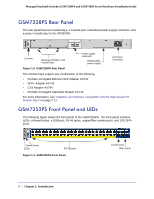
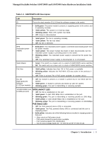
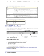
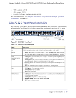
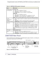
Managed Stackable Switches GSM7200PS and GSM7300S Series Hardware Installation Guide Table 1-3. GSM7252PS LED Description (Continued) LED Description ports • Off: No SFP module link is established on the port. • Solid green: A valid 1000 Mbps SFP module link is established on the port. • Blinking green: The port is transmitting or receiving packets at 1000 Mbps. • Solid yellow: A valid 100 Mbps SFP module link is established on the port. • Blinking yellow: The port is transmitting or receiving packets at 100Mbps. Note: If port 43~48 media is changed to copper, the SFP LEDs change to Off status. SFP+ Ports • Off: No SFP module link is established on the port. (1 Link/ACT LED per • Solid green: A valid 10 Gbps SFP+ module link is established on the port. port) • Blinking green: The port is transmitting or receiving packets at 10Gbps. Table 1-4. GSM7252PS Port PoE Power Specification Port 1-8 9-48 Power Range 0w - 30w 0w - 15.4w GSM7252PS Rear Panel The rear panel has two module bays, a redundant power supply connector, a console port, and a power module bay for the APS525W. Power receptacle Console Stacking/XFP/SFP+/CX4 module bays Redundant power supply connector Replaceable power supply Figure 1-4 GSM7252PS Rear Panel The module bays support any combination of the following: • ProSafe 10-Gigabit Ethernet XFP Adapter (AX741) • SFP+ Adapter AX743 • CX4 Adapter AX744 • ProSafe 24-Gigabit Stackable Module AX742. For more information, see "Adapters and Modules Compatible with the High-Speed I/O Module Bays" on page 2-21. 10 | Chapter 1: Introduction
-
 1
1 -
2
-
3
-
4
-
 5
5 -
 6
6 -
 7
7 -
 8
8 -
 9
9 -
 10
10 -
 11
11 -
 12
12 -
 13
13 -
 14
14 -
 15
15 -
16
-
17
-
18
-
19
-
20
-
21
-
22
-
23
-
24
-
25
-
26
-
27
-
28
-
29
-
30
-
31
-
32
-
33
-
34
-
35
-
36
-
37
-
38
-
39
 |
 |
