Netgear GSM7252PS GSM72xxPS and GSM73xxSv2 Series Managed Switch Hardware Inst - Page 6
Introduction
 |
UPC - 606449071665
View all Netgear GSM7252PS manuals
Add to My Manuals
Save this manual to your list of manuals |
Page 6 highlights
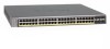
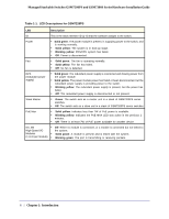
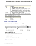
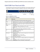
Managed Stackable Switches GSM7200PS and GSM7300S Series Hardware Installation Guide Table 1-1. LED Descriptions for GSM7228PS LED Description ID This is the stack member ID (1-8) that the software assigns to the switch. Power • Solid green: The power module is present, is supplying power to the switch, and is working normally. • Solid yellow: The system is in boot-up stage. • Blinking yellow: POS/CPU system has failed. • Off: Power is disconnected. Fan • Solid green: The fan is operating normally. • Solid yellow: The fan has failed. • Off: No fan is detected. RPS (redundant power supply) • Solid green: The redundant power supply is connected and drawing power from the power module. • Solid yellow: The power module power has failed or been disconnected, but the redundant power supply is providing power to the switch. • Blinking yellow: The redundant power supply is present, but the power has failed. • Off: The redundant power supply is disconnected or not present. Stack Master • Green: The switch acts as a master unit in a stack of GSM7200PS series switches. • Off: The switch acts as a slave unit in a stack of GSM7200PS series switches. PoE Max • Solid yellow: Indicates less than 7W of PoE power is available. • Blinking yellow: Indicates the PoE MAX LED was active in the previous 2 minutes. • Off: There is at least 7W of PoE power available for another device. M1, M2 High-Speed I/O Modules (1 LED per module) • Off: Either no module is connected, or a module is connected but not linked to the system. • Solid green: A module is present and is linked with the system. • Blinking green: The port is transmitting or receiving packets. 6 | Chapter 1: Introduction
-
 1
1 -
 2
2 -
 3
3 -
 4
4 -
 5
5 -
 6
6 -
 7
7 -
 8
8 -
 9
9 -
 10
10 -
 11
11 -
 12
12 -
13
-
14
-
15
-
16
-
17
-
18
-
19
-
20
-
21
-
22
-
23
-
24
-
25
-
26
-
27
-
28
-
29
-
30
-
31
-
32
-
33
-
34
-
35
-
36
-
37
-
38
-
39
 |
 |
