Netgear SB104 Installation Guide - Page 4
Install the Hub - manual
 |
UPC - 606449000825
View all Netgear SB104 manuals
Add to My Manuals
Save this manual to your list of manuals |
Page 4 highlights
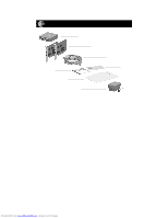
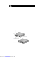
Install the Hub 1. Set the hub on a flat surface or mount it on a wall and choose a location that: • Is close to an electrical outlet. • Exposes the front and rear panels to allow connection of the network cables and easy monitoring of the LEDs. • Places the hub and PCs close enough to connect the network cables. To install the hub on a wall, measure the distance between the mounting holes at the back of the hub and mark the wall to match the location of the mounting holes. Drill pilot holes at the two marked locations on the wall and screw two 5/16-inch diameter flathead screws (provided) into the wall so that the screws protrude 1/18 inch to 3/16 inch. Slide the hub down onto the screws. 2. Turn on power to the hub by connecting the power adapter. 3. Verify that the Pwr (power) LED is on. If the Pwr LED is not on, the hub is defective and should be returned to your point-of-sale representative. 4. Make sure that the Normal/Uplink push button is set to Normal. The push button is set to Uplink only if port 4 is connected to another hub for expansion purposes. Link LED Rx LED Pwr LED Col LED RJ-45 ports Normal/Uplink push button (Normal position when connected to a PC) Ground clip (not used) Power adapter receptacle 7979FB Model SB104 10 Mbps Network Starter Kit Installation Guide Downloaded from www.Manualslib.com manuals search engine
-
 1
1 -
 2
2 -
 3
3 -
 4
4 -
 5
5 -
 6
6 -
 7
7 -
 8
8 -
 9
9 -
 10
10 -
11
-
12
-
13
-
14
-
15
 |
 |
