NordicTrack 9600 Elliptical Trainer Uk Manual - Page 6
How To Assemble The Elliptical Trainer - personal trainer
 |
View all NordicTrack 9600 Elliptical Trainer manuals
Add to My Manuals
Save this manual to your list of manuals |
Page 6 highlights
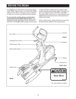
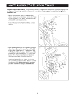
HOW TO ASSEMBLE THE ELLIPTICAL TRAINER Assembly requires two persons. Set the elliptical trainer in a cleared area and remove all packing materials. Do not dispose of the packing materials until assembly is completed. Assembly can be completed using the included hex keys. 1. Lift the Left Handlebar Arm (17) to the position shown. Attach the Left Handlebar Arm to the Frame (1) with two 3/8" x 1 1/4" Button Head Screws (48) and two 3/8" Lock Washers (100). Repeat this step for the Right Handlebar Arm (not shown). 1 1 100 48 17 100 2. Have another person hold the Upright (2) in the po- 2 sition shown. Connect the Lower Power Wire (96) to the Upper Power Wire (97). Connect the Lower CATV Cable (102) to the Upper CATV Cable (101). Connect the Lower Battery Wire (77) to the Upper Battery Wire (78). Connect the Lower Controller Wire (80) to the Upper Controller Wire (79). Attach the Upright (2) to the Frame (1) with four 3/8" x 1 1/4" Button Head Screws (48) and four 3/8" Star Washers (85). Make sure that no wires are pinched between the Upright and the Frame. 48 85 97 96 2 101 78 79 77 80 1 102 48 85 48 85 5
-
 1
1 -
 2
2 -
 3
3 -
 4
4 -
 5
5 -
 6
6 -
 7
7 -
 8
8 -
 9
9 -
 10
10 -
 11
11 -
 12
12 -
13
-
14
-
15
-
16
-
17
-
18
-
19
-
20
-
21
-
22
-
23
-
24
-
25
-
26
-
27
-
28
-
29
-
30
-
31
-
32
-
33
 |
 |
