NordicTrack C2420 Treadmill English Manual - Page 8
The connectors should
 |
View all NordicTrack C2420 Treadmill manuals
Add to My Manuals
Save this manual to your list of manuals |
Page 8 highlights
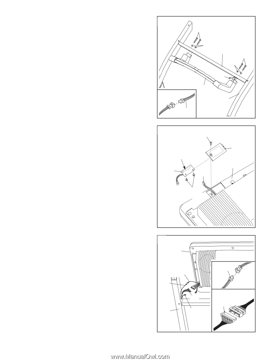
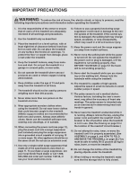
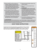
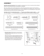
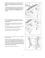
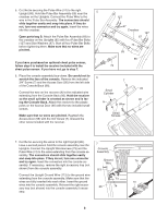
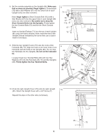
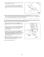
5. Cut the tie securing the Pulse Wire (74) to the right Upright (85). Hold the Pulse Bar Assembly (69) near the crossbar on the Uprights. Connect the Pulse Wire to the wire in the Pulse Bar Assembly. The connectors should slide together easily and snap into place. If they do not, turn one connector and try again. Insert the wires into the crossbar. Open parts bag B. Attach the Pulse Bar Assembly (69) to the crossbar on the Uprights (85) with four Pulse Bar Bolts (127) and Star Washers (67). Start all four Pulse Bar Bolts before tightening them. Make sure that no wires are pinched. If you have purchased an optional chest pulse sensor, follow step 6 to install the receiver included with the chest pulse sensor. If you have not, go to step 7. 6. Place the console assembly face-down. Be careful not to scratch the face of the console. Remove the indicated 3/4" Screw (7) and the Access Door (95) from the left side of the Console Back (96). Connect the wire on the receiver (A) to the indicated wire extending from the Console Back (96). Hold the receiver so the small cylinder is oriented as shown and is facing the Console Back. Attach the receiver to the plastic posts on the Access Door (95) with the two included small screws. Make sure that no wires are pinched. Reattach the Access Door (95) with the 3/4" Screw (7). Discard the other wires included with the receiver. 5 127 67 Crossbar 127 67 74 69 85 74 6 7 95 Small Cylinder 96 A Wire Small Screws 7. Cut the tie securing the wires to the right Upright (85). Have a second person hold the console assembly near the 7 Uprights. Connect the Upright Wire Harness (73) and the Console Pulse Wire (74) to the wires extending from the console as- Assembly sembly. The connectors should slide together easily and snap into place. If they do not, turn one connector and try again. Insert the connectors into the console as- Ground Wire 74 sembly. If necessary, remove the right accessory tray (not shown) from the console assembly. 113 Connect the Upright Ground Wire (113) to the ground wire extending from the console assembly. Make sure that the 73 wires are fully inserted into each other. Insert the ground 73 wires into the console assembly. Reinsert the right accessory tray (not shown) into the console assembly if neces- 85 74 sary. 8
-
 1
1 -
2
-
 3
3 -
 4
4 -
 5
5 -
 6
6 -
 7
7 -
 8
8 -
 9
9 -
 10
10 -
 11
11 -
 12
12 -
 13
13 -
14
-
15
-
16
-
17
-
18
-
19
-
20
-
21
-
22
-
23
-
24
-
25
-
26
-
27
-
28
-
29
-
30
-
31
-
32
-
33
-
34
-
35
-
36
-
37
-
38
 |
 |