Panasonic AG-HPX600PJ Operating Instructions - Page 70
Supplying time codes to external devices
 |
View all Panasonic AG-HPX600PJ manuals
Add to My Manuals
Save this manual to your list of manuals |
Page 70 highlights
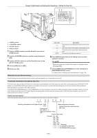
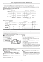
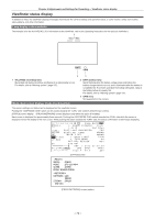
Chapter 4 Adjustments and Settings for Recording - Setting the time data ffWhen the time code is externally locked, the time code is instantaneously locked to the external time code, the same value as the value of the external time code is output to the counter display area, and the [TC] display is inverted. Do not set to the recording mode for several seconds until the sync generator has stabilized. ffOnce the time code is slaved, the slave state* is maintained even if there are no longer inputs to the or terminal. However, the slave state is canceled in the following instances: - When [TC PRESET] has been performed - When the power is turned off - When [TC MODE] has been switched - When [TC_MD] has been set to [R‑RUN] on the [SET01:TC/UB] screen of SmartUI - When [REC FORMAT] and [CAMERA MODE] have been switched * Slave function refers to locking of the time code to TC IN input and making the time code continue as it is even if the time code is discontinued. Setting of user bits when the time code is externally locked To externally lock user bits, set the [UB MODE] item on the setting menu [RECORDING SETUP] screen to [EXT]. The user bits are slaved to the user bit values input to the terminal regardless of [F‑RUN]/[R‑RUN]. For details, refer to "Setting the time data" (page 63), "User bits settings" (page 66). Canceling the external lock Stop supply of the external time code, and set the [UB MODE] item on the setting menu [RECORDING SETUP] screen to other than [EXT]. Cautions when switching the power supply from the battery to the external power supply while an external lock is active To keep the time code generator power supply on continuously, connect an external power supply to the terminal and then remove the battery pack. If the battery pack is removed first, there is no guarantee that the time code will stay externally locked. External synchronization of the camera unit while an external lock is active While an external lock is active, the generator lock is activated on the camera unit by the reference video signal input to the terminal. @@NOTE tt To externally lock multiple units with the camera as the master device, set to the same setting as on the setting menu [CAMERA MODE] screen on the camera. Note that in a system using a mixture of interlaced and progressive scanning, the continuity of the video and time codes is not guaranteed. tt When externally locking in the 24P, 24PA and 24PN (native) modes, be sure to input non-drop frame time codes. An external lock is not possible using drop frames. Also, images may be disrupted the instant that the external lock is activated, though this is due to alignment of the 5-frame cycle and is not a malfunction. Supplying time codes to external devices To supply the time code output according to the camera image or the playback image to a VTR or other recording devices, set the [TC IN/OUT SEL] item on the setting menu [IN/OUT SEL] screen to [TC OUT], and the [TC VIDEO SYNC] item to [VIDEO OUT]. Also, set the [GL PHASE] item on the setting menu [OTHER FUNCTIONS] screen to [HD SDI] or [COMPOSITE] according to the video output to be supplied, and set the [TC OUT] item on the [IN/OUT SEL] screen to [TCG/TCR]. AG-HPX600P/AG-HPX600EJ/AG-HPX600EN Composite output SDI output Time code output Time code input Video input SDI input HD SDI input VTR, etc. @@NOTE tt When the [TC VIDEO SYNC] item is set to [VIDEO OUT], the input time code is output according to the delayed video output. - 70 -
-
 1
1 -
2
-
3
-
4
-
5
-
6
-
7
-
8
-
9
-
10
-
11
-
12
-
13
-
14
-
15
-
16
-
17
-
18
-
19
-
20
-
21
-
22
-
23
-
24
-
25
-
26
-
27
-
28
-
29
-
30
-
31
-
32
-
33
-
34
-
35
-
36
-
37
-
38
-
39
-
40
-
41
-
42
-
43
-
44
-
45
-
46
-
47
-
48
-
49
-
50
-
51
-
52
-
53
-
54
-
55
-
56
-
57
-
58
-
59
-
60
-
61
-
62
-
63
-
64
-
 65
65 -
 66
66 -
 67
67 -
 68
68 -
 69
69 -
 70
70 -
 71
71 -
 72
72 -
 73
73 -
 74
74 -
 75
75 -
76
-
77
-
78
-
79
-
80
-
81
-
82
-
83
-
84
-
85
-
86
-
87
-
88
-
89
-
90
-
91
-
92
-
93
-
94
-
95
-
96
-
97
-
98
-
99
-
100
-
101
-
102
-
103
-
104
-
105
-
106
-
107
-
108
-
109
-
110
-
111
-
112
-
113
-
114
-
115
-
116
-
117
-
118
-
119
-
120
-
121
-
122
-
123
-
124
-
125
-
126
-
127
-
128
-
129
-
130
-
131
-
132
-
133
-
134
-
135
-
136
-
137
-
138
-
139
-
140
-
141
-
142
-
143
-
144
-
145
-
146
-
147
-
148
-
149
-
150
-
151
-
152
-
153
-
154
-
155
-
156
-
157
-
158
-
159
-
160
-
161
-
162
-
163
-
164
-
165
-
166
-
167
-
168
-
169
-
170
-
171
-
172
-
173
-
174
-
175
-
176
-
177
-
178
 |
 |
