Panasonic SAHT730 Technical Guide - Page 10
Sensor testing - sa ht730 error
 |
View all Panasonic SAHT730 manuals
Add to My Manuals
Save this manual to your list of manuals |
Page 10 highlights
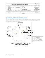
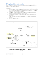
6. Sensor testing These 7 electrical parts could cause transport problems but so can a broken mechanical part. Test all 5 sensors and 2 motors as a group once the tray is removed. If the parts test OK, the problem is mechanical or a ribbon cable is bad. Testing the Tray Loading Motor and Related Sensors With the tray removed (section 4), install the front panel to test the tray loading operation. Plug in front panel ribbon cables CN2008 and CN2009. Part 1. Tray in - out loading motor 2. Tray out sw. S9001 3. Main gear position Q9001 Setup 1. Rotate the main gear to the disc clamped position. 2. Press power on. Unplug the unit from AC power. Press the poweron button. Testing Parts 1/2 Do / Watch After laser focus searches ("INIT"), the loading motor turns to drive the transport to the non-clamped position ("WAIT"). The unit will then shut down ("H01 error"). Measure the resistance between CN2011 / pin 1 and pin 2. Rotate the main gear to the position shown in figure 4 inset so that you can see the sensor in the cutout. Rocking the gear changes Q9001's logic state. Table 4 Proof the part is good Motor must turn belt and the main black gear into the disc unclamped position. Motor resistance = 14 ohms. Motor volts = 8Vdc. Between CN2011/pins 8 & 10. The switch is normally open but shorted when pressed (simulates tray out). The voltage at CN2011/pin 6 will change from 0.1Vdc to 4.6Vdc as you rotate the main gear to block Q9001's light. Q9001 Main gear position sensor test CN2011 / pin 6 = 0.1V - 4.6Vdc as gear is rotated Inset Main black gear position for Q9001 sensor inspection Main gear position sensor S9001 S9001 tray in / out test Shorted - Tray out Open - Tray in [Front panel displays the words "Open" or "Close".] Figure 4 - Loading (Tray In - Out) Motor Circuit Cutout shows Q9001 SA-HT730 / SAHT930 10
-
 1
1 -
2
-
3
-
4
-
 5
5 -
 6
6 -
 7
7 -
 8
8 -
 9
9 -
 10
10 -
 11
11 -
 12
12 -
 13
13 -
 14
14 -
 15
15 -
16
-
17
-
18
-
19
-
20
-
21
-
22
-
23
 |
 |
