Panasonic SAHT730 Technical Guide - Page 8
Tray Removal for Sensors, Belts, & Diagnostic Access - sa ht730 system cable
 |
View all Panasonic SAHT730 manuals
Add to My Manuals
Save this manual to your list of manuals |
Page 8 highlights
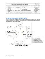
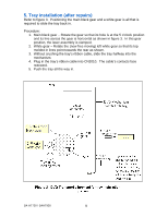
4. Tray Removal for Sensors, Belts, & Diagnostic Access Removing the tray to access the sensors and motor first requires removing the tray trim, and then the front panel (not shown) before the tray assembly will come out. Follow figure 2 for easy tray removal. CAUTION - metal chassis edges are sharp. Quick Procedure: 1. Rotate the white Close Lock Gear / lever CW (clockwise) within the turntable platter to unlock the tray. Pull the tray forward (towards yourself) until it stops. 2. From the bottom of the black tray, remove the front silver trim piece (not shown). 3. Unplug the two front panel cables (CN2008 & CN2009) and remove the front panel (not shown). 4. On the main board, remove the cable (CN2010) attached to the tray. 5. Move the rear white lever counter-clockwise (CCW) as shown in figure 2 and at the same time 6. Release the two parallel tray stops (a and b) by pressing the larger tab (closest to you) inward toward the center of the tray (figure 2). 7. Slide the tray out towards yourself to expose the sensors, motors, and belt. 5. 6b 6a 1. 2. Remove trim from the bottom. Figure 2 - Tray removal revealed SA-HT730 / SAHT930 8 CN2010 Contacts = rear CN2008 Contacts = left CN2009 Contacts = rear
-
 1
1 -
2
-
 3
3 -
 4
4 -
 5
5 -
 6
6 -
 7
7 -
 8
8 -
 9
9 -
 10
10 -
 11
11 -
 12
12 -
 13
13 -
14
-
15
-
16
-
17
-
18
-
19
-
20
-
21
-
22
-
23
 |
 |
