Panasonic TH42PD25 TH37PD25 User Guide - Page 11
Cable Connection - video card
 |
View all Panasonic TH42PD25 manuals
Add to My Manuals
Save this manual to your list of manuals |
Page 11 highlights
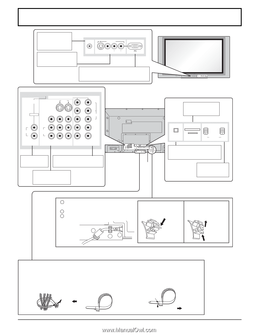
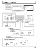
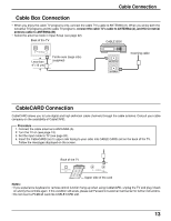
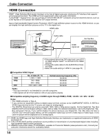
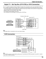
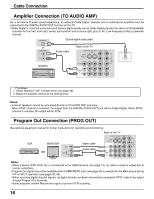
Cable Connection Headphones / Earphones jack (see page 17) Front AV terminals (see page 17) INPUT 3 HPJ S VIDEO VIDEO L AUDIO R From EXTERNAL monitor terminal on Computer (see page 18) MENU OK VOLUME CHANNEL VIDEO3 HPJ S-VIDEO VIDEO L AUDIO R PC AV IN COMPONENT VIDEO INPUT INPUT 1 1 2 S VIDEO PROG OUT HDmI VIDEO L AUDIO IN R L TO AUDIO AMP R 2 Y PB VIDEO PR HDMI terminal COMPONENT Input terminals (see page 14) (see page15) AV terminals (see pages 15, 16) CableCARD slot (see page 13) CABLE CARD DIGITAL AUDIO OUT SERVICE ONLY B ANTENNA A Cable In DIGITAL AUDIO OUT terminal (see page 16) Antenna terminals (see pages 12, 13) - AC cord fixing 1 Connect power plug to the socket of the main body. 2 Fix the left clamper. 3 Fix the right clamper. To fix: Push in till a To release: Pull up clicking sound is heard. while drawing the knob. 2 31 - Cable fixing bands Secure cables connected to terminals with bands as required. Wrap the cable fixing band around cables then pass the pointed end through the locking block, as shown in the figure. While ensuring there is sufficient slack in cables to minimize stress (especially in the power cord), firmly bind all cables with the supplied fixing band. To tighten: Pull To loosen: Push the catch Pull 11
-
 1
1 -
2
-
3
-
4
-
5
-
 6
6 -
 7
7 -
 8
8 -
 9
9 -
 10
10 -
 11
11 -
 12
12 -
 13
13 -
 14
14 -
 15
15 -
 16
16 -
17
-
18
-
19
-
20
-
21
-
22
-
23
-
24
-
25
-
26
-
27
-
28
-
29
-
30
-
31
-
32
-
33
-
34
-
35
-
36
-
37
-
38
-
39
-
40
-
41
-
42
-
43
-
44
-
45
-
46
-
47
-
48
-
49
-
50
-
51
-
52
-
53
-
54
-
55
-
56
-
57
-
58
-
59
-
60
-
61
-
62
-
63
-
64
-
65
-
66
-
67
-
68
-
69
-
70
-
71
-
72
 |
 |