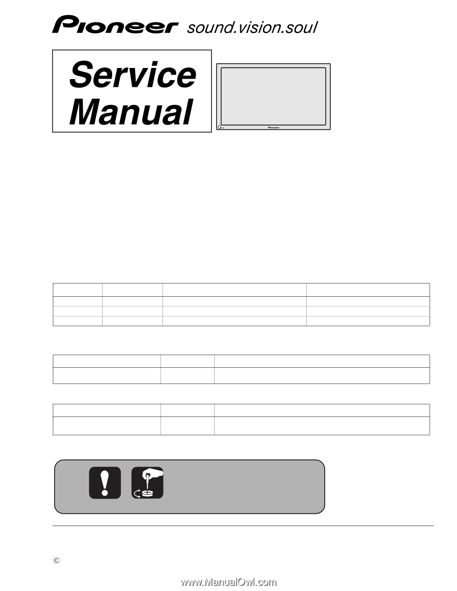
Pioneer 434CMX Service Manual
Pioneer 434CMX - PDP - 43" Plasma Panel Manual
 |
UPC - 012562691107
View all Pioneer 434CMX manuals
Add to My Manuals
Save this manual to your list of manuals |
Pioneer 434CMX manual content summary:
- Pioneer 434CMX | Service Manual - Page 1
- 240V AC100 - 240V This service manual should be used together with the following manual(s). Model No. Order No. Remarks PDP-434CMX, PDP-43MXE1 PDP-43MXE1-S ARP3199 SCHEMATIC DIAGRAM, PCB CONNECTION DIAGRAM Refer to the following service manual for video card. Model No. Order No. Remarks - Pioneer 434CMX | Service Manual - Page 2
do so and refer the repair to a qualified service technician. WARNING This product contains lead in solder and certain electrical parts contain chemicals which are known to the state of this may cause a high risk of disturbance to TVs and radios in the surrounding. F 2 PDP-434CMX 1 2 3 4 - Pioneer 434CMX | Service Manual - Page 3
Model 229 equivalent)", measure for current from all exposed metal parts PIONEER recommended replacement one, shown in the parts list in this Service Manual, may create shock, fire or other hazards. B Product Safety is continuously under review and new instructions PDP-434CMX 3 5 6 7 8 - Pioneer 434CMX | Service Manual - Page 4
the Charged Section. C 43 SCAN B Assy 43 Y DRIVE Assy POWER SUPPLY Unit 43 X DRIVE Assy X CONNECTOR B Assy D E 43 SCAN A Assy Power Switch (S1) AC Inlet with Filter X CONNECTOR A Assy Power Cord F Fig.1 Charged Section and High Voltage Generating Point (Rear View) 4 PDP-434CMX 1 2 3 4 - Pioneer 434CMX | Service Manual - Page 5
glue may lead to failures or troubles in the product. By following the instructions in this manual, be sure to apply the prescribed grease or glue to proper portions by the appropriate amount.For replacement parts or tools, the prescribed ones should be used. C D E F PDP-434CMX 5 5 6 7 8 - Pioneer 434CMX | Service Manual - Page 6
2.6 TERMINAL PANEL and REAR SECTION ...18 2.7 FRONT SECTION...20 2.8 PANEL CHASSIS (43) ASSY (AWU1098)...22 2.9 PDP SERVICE ASSY 434CMX (AWU1094 23 3. BLOCK DIAGRAM AND SCHEMATIC DIAHRAM (Refer to "Service Manual: ARP3199 24 3.1 BLOCK DIAGRAM ...24 B 3.1.1 OVERALL BLOCK DIAGRAM (1/2) ...24 - Pioneer 434CMX | Service Manual - Page 7
clamps 2 Standby power consumption 1 W (PDP-43MXE1) Bead bands 2 B (PDP-43MXE1-S) Warranty 1 (PDP-434CMX Only) External dimension ...........1070 (W) x 630 (H) x 98 (D) mm Operating Instructions 1 42-1/8 (W) x 24-13/16 (H) x 3-7/8 (D) Display stands 2 (D: Not including handles) in - Pioneer 434CMX | Service Manual - Page 8
(In the case of no amount instructions, apply as you think it appropriate.) 2.1 PACKING B 1 C 2 3 D 27 5 E 6 8 PDP-434CMX Only F 8 1 PDP-434CMX Only 26 23 24 PDP-434CMX Only 9 10 11 PDP-43MXE1, PDP-43MXE1-S Only 30 31 32 33 35 29 28 PDP-434CMX Only 7 4 2 PDP-434CMX 2 15 17 18 16 34 - Pioneer 434CMX | Service Manual - Page 9
27 Caution Sheet 28 Image Stick Caution 29 Accessory C.Assy 4CMX 30 Plasma Caution Sheet 31 Plasma Caution Sheet 32 33 NSP 34 35 Caution Sheet Caution Sheet Warranty Card Image Caution Sheet 8 Part No. AXX1060 WB80FZB A SMZ80H400FZB See Contrast table (2) See Contrast table (2) See Contrast - Pioneer 434CMX | Service Manual - Page 10
18 20 21 5 14 26 3 28 14 15 6 14 15 14 79 D 8 E 4 F 10 1 10 14 15 15 11 14 15 14 12 15 14 13 PDP-434CMX 2 3 4 - Pioneer 434CMX | Service Manual - Page 11
4 5 P. Chassis (43) Assy 43 ADDRESS Assy DIGITAL VIDEO Assy FPC (114P) Flexible Cable (J201) Part No. AWU1098 AWZ6793 AWV2100 AEC1879 16 PCB Spacer 17 PCB Support 18 PCB Spacer 19 PCB Support 20 Ferrite Clamp AEC1941 AEC1938 AEC1944 Card Spacer AEC1998 PDP-434CMX 5 6 7 8 A B C D E F 11 - Pioneer 434CMX | Service Manual - Page 12
1 2 3 4 2.3 CHASSIS SECTION (2) A 20 8 100V 100V: for PDP-434CMX 200V: for PDP-43MXE1 PDP-43MXE1-S 14 19 15 15 15 B 19 32 10 9 Upper side 20 19 200V 32 15 15 15 31 31 19 9 11 29 30 23 3 24 15 25 22 15 Upper side 15 15 C 28 27 26 D E 21 17 16 - Pioneer 434CMX | Service Manual - Page 13
43 X DRIVE Assy 43 Y DRIVE Assy POWER SUPPLY Unit X CONNECTOR B Assy X CONNECTOR A Assy Part No. AWZ6840 AWV2022 AXY1083 AWZ6799 AWZ6798 NSP 6 NSP 7 8 > 9 10 43 SCAN A Assy 43 ADX2902 ANG2623 ANG2625 31 Screw 32 Locking Wire Saddle AMZ30P080FMC AEC1948 PDP-434CMX 5 6 7 8 A B C D E F 13 8 - Pioneer 434CMX | Service Manual - Page 14
B 8 25 10 Upper side 9 10 11 C 11 15 26 17 16 D 16 17 24 7 7 7 7 24 7 7 Rear view 6 E 22 19 14 19 12 23 13 2 F 1 14 1 PDP-434CMX 2 3 14 3 20 21 Bottom view 4 - Pioneer 434CMX | Service Manual - Page 15
2 KEY CONTROL Assy 3 LED OPT Assy 4 5 Part No. AWZ6855 AWZ6853 AWZ6957 NSP 6 7 8 9 10 Front Chassis H (43) Front Spacer (CMX) Rear Frame (43M) Locking Wire Saddle Locking Wire Saddle Case Spacer BBZ30P050FMC AMR3411 AMR3407 PMB30P060FNI AMR3431 AMR3430 PDP-434CMX 5 6 7 8 A B C D E F 15 8 - Pioneer 434CMX | Service Manual - Page 16
A 29 14 5 B 31 4 7 8 C 97 7 3 4 32 28 28 28 23 24 25 25 3 30 2627 30 27 30 7 7 7 79 34 11 12 Bottom view 6 10 12 10 25 18 13 19 20 16 13 21 29 14 15 D 22 11 15 11 33 33 11 10 23 2 26 1 29 E 28 28 F 16 PDP-434CMX 1 2 3 4 - Pioneer 434CMX | Service Manual - Page 17
B 32 Video Stay ANG2607 33 Gasket M-T150 ANK1741 34 Shield Sheet AEC2004 16 15P/16P Wire (J106) ADX2907 17 18 10/11P Housing Wire (J110) ADX2912 19 10P Housing Wire (J113) ADX2908 20 12P Housing Wire (J112) ADX2892 C (2) CONTRAST TABLE PDP-434CMX/LUC, PDP-43MXE1/LDFK and PDP-43MXE1 - Pioneer 434CMX | Service Manual - Page 18
18 28 18 26 18 18 18 18 18 18 18 29 18 18 18 18 36 (2/4) 30 32 30 31 32 18 18 18 30 36 (3/4) 27 33 34 35 C 7 18 89 8 18 17 17 18 18 2 D 18 1 24 66 20 20 19 20 20 19 25 25 18 Rear view F 11 18 16 15 18 1 13 13 14 14 PDP-434CMX 2 3 21 18 18 25 25 10 11 4 - Pioneer 434CMX | Service Manual - Page 19
Part No. > 21 Power Switch (S1) ASG1094 22 Housing Wire (MX)(J116) ADX2896 A 23 COMM Stay A ANG2605 24 COMM Stay B ANG2606 25 Screw APZ30P080FZK 6 Guide ANK1734 ANG2610 ABK1033 ABK1032 ABK1034 31 Grip 32 Screw 33 Terminal Label R (43M) TABLE PDP-434CMX/LUC, PDP-43MXE1/LDFK and PDP-43MXE1 - Pioneer 434CMX | Service Manual - Page 20
1 2 3 4 2.7 FRONT SECTION A 4 B 3 6 6 13 14 6 3 14 8 C 13 4 14 5 6 6 14 6 D 2 15 9 7 PDP-434CMX Only E 18 17 16 1 10 12 11 F 20 PDP-434CMX 1 2 3 4 - Pioneer 434CMX | Service Manual - Page 21
following: Mark No. Symbol and Description 7 Display Label 8 Front Case 434 (CMX) 8 Front Case 434S (CMX) 9 Energy Star Label PDP-434CMX/ LUC AXX2836 AMB2790 Not used AAX2856 PDP-43MXE1/ LDFK Not used AMB2790 Not used AAX2856 PDP-43MXE1-S/ LDFK Not used Not used AMB2791 AAX2865 16 Lead Cover - Pioneer 434CMX | Service Manual - Page 22
Assy Part No. AWV2120 AWZ6793 AWV2023 AWZ6796 AWZ6797 AWZ6798 AWZ6799 NSP B NSP NSP NSP NSP Address Module (IC1-IC30) Plasma Panel Assy (43")(V1) FPC (43XGA-X) FPC (43XGA-Y) Chassis Assy (43) AXF1124 AAV1250 ADY1079 ADY1080 ANA1773 C NSP NSP NSP NSP NSP PCB Spacer PCB Support Edge Card Spacer - Pioneer 434CMX | Service Manual - Page 23
5 6 7 2.9 PDP SERVICE ASSY 434CMX (AWU1094) PDP SERVICE Assy (AWU1094) • Parts List Mark No. Description NSP NSP P. Chassis (43) Assy Front Chassis H (43) F Chassis VL (43M) F Chassis VR (43M) Rear Frame (43M) Part No. AWU1098 ANA1714 ANA1755 ANA1756 ANG2613 NSP Sub Frame L Assy (43M) - Pioneer 434CMX | Service Manual - Page 24
V+3V_D DIGITAL VIDEO ASSY V+12V DCLK, DE HD, VD RA IN 43 ADDRESS ASSY IC1501 V+3V_LVDS V+3V_PLL V+3V_IC5 RESONANCE BLOCK V+ADR V+9V V+60V DRIVER IC IC1552 DRIVER IC IC1553 DRIVER IC IC1554 DRIVER IC IC1555 DRIVER IC IC1552 DRIVER IC IC1553 DRIVER IC IC1554 DRIVER IC IC1555 PDP-434CMX - Pioneer 434CMX | Service Manual - Page 25
V+ADR V+9V V+60V V+5V CN1501 AD1 43 ADDRESS ASSY IC1501 V+3V_LVDS V+3V_PLL V+3V_IC5 RESONANCE BLOCK V+ADR V+9V V+60V DRIVER IC IC1552 DRIVER IC IC1553 DRIVER IC IC1554 DRIVER IC IC1555 DRIVER IC IC1552 DRIVER IC IC1553 DRIVER IC IC1554 DRIVER IC IC1555 PDP-434CMX 5 6 7 8 F 25 - Pioneer 434CMX | Service Manual - Page 26
5 F IC7801 VIDEO AMP IC7802 VIDEO AMP IC6255 PD0278A IC6107 PD0278A YCbCr HD/VD V+13V V+12V IC7902 2-1 SEL 6dB AMP YCbCr RGB HV V+3V IC7803 3-1 SEL L/R VIDEO SLOT 1 ASSY or VIDEO SLOT 2 ASSY CN7902 CN8954 CN8952 VS2 VS4 VS3 VS5 VS1 VIDEO SLOT I/F ASSY CN8951 26 PDP-434CMX 1 2 3 4 - Pioneer 434CMX | Service Manual - Page 27
LPF IC6602 A/D PLL H/V IC7207 MAIN D UCOM H/V CN7406 CN7405 R12 H/V IC6604 H/V IC6603 SYNC SEP H/V SELECTOR H/V IC6607 H/V R11 SELECTOR E R4 H/V H/V IC7201 IC7204 H/V SELECTOR CN7410 CN7407 RGB ASSY F PDP-434CMX 27 5 6 7 8 - Pioneer 434CMX | Service Manual - Page 28
4 3 2 1 PDP-434CMX 28 F OUTPUT D-SUB D-SUB INPUT 1 AN5870 75Ω SW AN5870 75Ω SW INPUT 2 DVI BA7078 SYNC SEP. COMPOSITE SYNC H, V 5 → 3.3V 74VHC125 IC7004 PE5362A IP VIDEO PROCESS IC7101 PD5855A MULTI PROCESS FRC NR IC5401 PD5856A LVDS Sequence SYNC PROCESS SYNC PROCESS MANTA - Pioneer 434CMX | Service Manual - Page 29
Y DRIVE ASSY From DIGITAL VIDEO ASSY CN2001 43 Y DRIVE ASSY IC5V Y1 CLK1 CE CLK2 CLR OC2 OC1 SI Photo Coupler Photo Coupler Photo VF+ VF- IC5V VOFS OVP VOFS VOFS VOFS UVP D-D CONV. VSUS VH OVP VH D-D VH UVP CONV. VH PDP-434CMX 5 6 7 A B C To SCAN ASSY D E F 29 8 From POWER SUPPLY UNIT - Pioneer 434CMX | Service Manual - Page 30
To X CONNECTOR ASSY 1 2 3 4 3.1.5 43 X DRIVE ASSY A 43 X DRIVE ASSY X1 From DIGITAL VIDEO ASSY CN1001 XSUS-G XSUS-B XSUS-U2 XSUS-D2 XSUS-U1 XSUS-D1 P.D. D-D CONV. VRN-220V SUSGND 11 T1401 N.C. 12 VRN UVP P.D. XNR P.D. DET. From POWER SUPPLY UNIT E F 30 PDP-434CMX 1 2 3 4 - Pioneer 434CMX | Service Manual - Page 31
MODEL 43 X DRIVE ASSY MUTE PD PD PD Connector disconnection detection PANEL SENSOR ASSY Thermal sensor AC_DET DRIVE_OFF PD_TRG RELAY PD LED P8 POWER SUPPLY ASSY STB_MT STB3.3V Power DRIVE OFF AC_DET AC-OFF Det. 5 RELAY CONTROL POWER ON RELAY OR Each PD Vsus PDP-434CMX 6 7 Video - Pioneer 434CMX | Service Manual - Page 32
4 V+3V V+12V AV1 CN7601 V+6.5V L+ R+ L- R- KEY AV2 CN8702 AV3 CN8703 LED OSC AV5 CN8704 TXD, RXD AV4 CN7605 RGB V/H RGB V/H CN8705 V+6.5V V+3.3V_STB V+3.3V V+5V E F 32 PDP-434CMX 1 2 3 4 - Pioneer 434CMX | Service Manual - Page 33
74HC125 IC7004 PE5362A IP IC7101 PD5855A VIDEO PROCESS X7001 OSC MULTI PROCESS FRC NR IC7001 SDRAM 2 64M IC7002 1 SDRAM 64M R10 CN7101 IC7102 EEP ROM TXD_MD RXD_MD SYNC PROCESS SYNC PROCESS MANTA 6 6 PDP-434CMX 7 E INPUT1 INPUT5 HD/VD HD/VD 7 R12 CN7405 BUFFER IC6601 SM5301BS - Pioneer 434CMX | Service Manual - Page 34
IC9455 IC9453 IC9455 TXD_CARD TXD_PDP IC9455 RXD_CARD IC9452 IC9452 IC9452 IC9452 FIRST RXD CB_MUTE SL LINK SR IN SR OUT SR SW INT_EXT GET_UART 34 PDP-434CMX 1 2 3 4 - Pioneer 434CMX | Service Manual - Page 35
(HD) CH2: K5004 (DE) V: 2V/div. H: 40nsec/div. CH1 CH2 4 CH1: K5002 (HD) CH2: CN5001-pin 77 (DCLK) V: 2V/div. H: 40nsec/div. CH1 CH2 2 CH1: K5003 (VD) CH2: K5004 (DE) V: 2V/div. H: 4µsec/div. CH1 CH2 5 CH1: K5003 (VD) CH2: CN5001-pin 88 (RA_IN2) V: 2V/div. H: 2msec/div. CH1 CH2 CH2 PDP-434CMX - Pioneer 434CMX | Service Manual - Page 36
of C6609 (BAIN) V: 200mV/div. H: 4µsec/div. V: 200mV/div. H: 4µsec/div. 19 Foot of R6628 (DATACK) V: 1V/div. H: 10nsec/div. CH1 CH1 F CH2 CH2 36 PDP-434CMX 1 2 3 4 - Pioneer 434CMX | Service Manual - Page 37
pin 9 (VD_IO) V: 2V/div. H: 4msec/div. 11 IC7601-pin 12 (L_AUDIO) V: 200mV/div. H: 400µsec/div. 10 CH1: JA7606-pin 13 (HD) V: 2V/div. H: 4µsec/div. 6 CH2: JA7606-pin 1 (R) V: 200mV/div. H: 4µsec/div. 12 IC7603-pin 14 (L_AUDIO) V: 200mV/div. H: 400µsec/div. CH1 CH2 PDP-434CMX 5 6 7 E F 37 8 - Pioneer 434CMX | Service Manual - Page 38
CLR) - K2029 (DGND) CH6: K2003 (CLK2) - K2029 (DGND) CH7: K2008 (LE) - K2029 (DGND) (43 Y DRIVE ASSY) V: 1V/div. H: 2msec/div. CH2 CH1 CH3 C CH4 CH2 CH5 CH6 CH3 CH7 3 Sustain K2023 (YPR-U) - K2010 (DGND) V: 1V/div. H: 2msec/div. (43 Y DRIVE ASSY) CH1 CH2 CH3 CH4 F 38 PDP-434CMX 1 2 3 4 - Pioneer 434CMX | Service Manual - Page 39
VIDEO, Signal: B/W(1×8)) CH1 CH2 CH3 CH1 CH2 CH3 H: 2msec/div. CH1 CH2 CH3 H: 500nsec/div. CH1 CH2 CH3 H: 2msec/div. CH1 CH2 CH3 H: 500nsec/div. CH1 CH2 CH3 H: 2msec/div. H: 500nsec/div. C 43 CH3 H: 500nsec/div. CH1 CH2 CH3 H: 2msec/div. H: 500nsec/div. F PDP-434CMX 39 5 6 7 8 - Pioneer 434CMX | Service Manual - Page 40
4 43 ADDRESS ASSY • ADR LOGIC BLOCK A 1 CH1: IC1552-pin 18 (CLK input) CH2: IC1552-pin 16 (LE input) CH3: IC1552-pin 9 (DATA input) V: 1V/div. (Input: VIDEO, 1V/div. (Input: VIDEO, Signal: Color-bar) CH1 CH2 CH3 CH1 C CH2 CH3 H: 2msec/div. H: 50µsec/div. D E F 40 PDP-434CMX 1 2 3 4 - Pioneer 434CMX | Service Manual - Page 41
drive power (+61V) input I Address drive power (+61V) input Not connected − GND − GND I +6.5V power input − GND Voltages at NTSC Signal Input +61VDC +61VDC +6.8VDC C D E F PDP-434CMX 41 5 6 7 8 - Pioneer 434CMX | Service Manual - Page 42
7 NC 4 Voltage (V) 0 0 13.6 13.6 12.9 12.9 0 3.3 0 3.3 3.3 0 VIDEO SLOT I/F ASSY VS1 (CN8951) Name No. GND 1 GND 2 V+13V 3 V+13V 4 V+12V 3.2 0 FAN (L), (R) FAN (L) Name No. FAN_12V 1 FAN_NG 2 GND 3 FAN (R) FAN_12V 1 FAN_NG 2 GND 3 F 42 PDP-434CMX 1 2 3 4 - Pioneer 434CMX | Service Manual - Page 43
CEC2 28 GND 29 HD_DVI 30 DE_DVI 31 GND 32 RB_DVI7 33 RB_DVI6 34 RB_DVI4 35 RB_DVI2 36 43 144 BB_DVI0 0/3.3 BB_DVI0 44 145 RA_DVI6 0/3.3 RA_DVI6 45 146 RA_DVI4 0/3.3 RA_DVI4 46 147 RA_DVI2 0/3.3 RA_DVI2 47 148 RA_DVI0 0/3.3 RA_DVI0 48 F PDP-434CMX 43 - Pioneer 434CMX | Service Manual - Page 44
DSUBV 41 GND 42 GND 43 IN5_VD 44 GND 45 GND 46 HYOUJI_X 47 VYOBI4 48 VYOBI5 49 VYOBI6 50 WE_ROM_B 4 Voltage (V) 0 0 5 0 0 3.3 0 0 0 0 0 0 0 VIDEO SLOT I/F ASSY VS3 ( 31 RB0_IC1 32 RB1_IC1 33 RB2_IC1 34 RB3_IC1 35 RB4_IC1 36 RB5_IC1 37 44 PDP-434CMX 1 2 3 4 - Pioneer 434CMX | Service Manual - Page 45
40 GND 41 GB0_IC1 42 GB1_IC1 43 GB2_IC1 44 GB3_IC1 45 GB4_IC1 46 (CN8702) No. Name 1 GND 2 KEY 3 V+3VSTB 8 VIDEO SLOT I/F ASSY Voltage (V) 0/3.3 VS4 (CN8953) Name BA4_IC1 No. KEY CONTROL ASSY KY1 (CN9001) Name No. GND 1 KEY 2 V+3VSTB 3 F PDP-434CMX 45 5 6 7 8 - Pioneer 434CMX | Service Manual - Page 46
V+6.5V 114 V+6.5V 115 GND 116 GND 117 V+3VSTB 118 V+3VSTB 119 NC 120 NC 121 NC 122 NC 123 NC 124 NC 125 46 PDP-434CMX 1 2 3 4 - Pioneer 434CMX | Service Manual - Page 47
25 HD_DET 26 GND 27 VD 28 GND 29 HD 30 GND 31 GND 32 RB0_IC1 33 RB1_IC1 34 RB2_IC1 35 RB3_IC1 36 RB4_IC1 VIDEO SLOT I/F ASSY VIDEO SLOT 1 and 2 ASSY VS5 (CN8954) No. Name 43 GB1_IC1 Voltage (V) 0/3.3 CN7902 Name GB1_IC1 No. A 43 GND 103 F PDP-434CMX 47 5 6 7 8 - Pioneer 434CMX | Service Manual - Page 48
GND 189 IN5_VD 190 HYOUJI_X 191 GPC3 192 GPC4 193 NC 194 VYOBI4 195 VYOBI5 196 VYOBI6 VIDEO SLOT 1 and 2 ASSY Voltage (V) CN7902 Name No. 0/3.3 RA0_IC1 161 0 GND 162 163 0 GPC4 192 0 NC 193 0 VYOBI4 194 0 VYOBI5 195 0 VYOBI6 196 48 PDP-434CMX 1 2 3 4 - Pioneer 434CMX | Service Manual - Page 49
CMX FUKUGO ASSY AWV2107 (PDP-434CMX type) NSP 1..CMX FUKUGO ASSY AWV2108 (PDP-43MXE1, PDP-43MXE1-S types) 2..AV I/O ASSY AWZ6894 (PDP-434CMX type) 2..AV I/O ASSY AWZ6895 (PDP-43MXE1, PDP VIDEO ASSY AWV2100 PCB PARTS LIST for PDP-434CMX/LUC Mark No. Description Part No. 43 ADDRESS - Pioneer 434CMX | Service Manual - Page 50
CONNECTOR A ASSY This assembly has no service part. X CONNECTOR B ASSY This assembly has no service part. 43 X DRIVE ASSY [X LOGIC BLOCK] 43 SCAN B ASSY SEMICONDUCTORS IC3201-IC3206 D3201 50 1 SN755864APZP KU10N16 [RESONANCE BLOCK] SEMICONDUCTORS IC1103 IC1101,IC1102 Q1113 PDP-434CMX - Pioneer 434CMX | Service Manual - Page 51
UDZS5.6B ATH1112 5 6 7 Mark No. L1202 L1203,L1206 Description 8 Part No. LFEA100J LFEA470J CAPACITORS C1214-C1217,C1227-C1230 C1233 (0.12/250V) C1244 R1414 R1420 R1403 R1401,R1404 R1417 VR1401 (1k) Other Resistors PDP-434CMX 7 AN1431M MIP161 TLP181(P-GR) 2SA1037K 2SC2412K EC11FS2 EC8FS6 UDZS5 - Pioneer 434CMX | Service Manual - Page 52
-D2205,D2207,D2208 D2213,D2214,D2216-D2219,D2222 4 Part No. 2SC2412K 2SK3560 2SK3723 CPH5506 1SS302 1SS355 EC11FS4 EC11FS4 ,C2216,C2217 CCSRCH331J50 C2230,C2232,C2233,C2235 CKSRYB104K16 C 43 Y DRIVE ASSY OTHERS 2002 CARD SPACER 2001 DRIVE SIRICON SHEET A 2001 PLATE Y 52 PDP-434CMX 1 2 3 4 - Pioneer 434CMX | Service Manual - Page 53
C2327 C2329,C2330 (1.5/300V) C2314 (0.047/250V) C2302 (0.1/630V) C2316,C2331 (300/280V) 6 Part No. ACE1163 ACE1163 ACE1165 ACG1092 ACH1359 C2303 (22/315V) C2336 (220/100V) C2306,C2334 C2308, Resistors CCP1390 RS1/16S###J OTHERS 2401 HEATSINK 2401 SCREW ANH1614 BBZ30P080FZK F PDP-434CMX 7 53 8 - Pioneer 434CMX | Service Manual - Page 54
Mark No. R7478 Description Other Resistors OTHERS CN7405 12P PLUG CN7401 15P PLUG CN7410 50P PLUG 4 Part No. RS1/16S8201F RS1/16S###J AKM1203 AKM1232 AKM1270 >IC7408, IC7409 >IC7405, IC7410 >IC7406, RS1/16S2200F RS1/16S3000F RS1/16S75R0F RS1/16S###J AKX9002 KM200NA6 54 PDP-434CMX 1 2 3 4 - Pioneer 434CMX | Service Manual - Page 55
Mark No. Description C6646, C6656-C6661 C6609, C6614, C6623 8 Part No. CKSRYB471K50 CKSRYB473K16 C6642 C6641 C6602 C6601 C6605-C6607, C6610, C6613 R5856, R5858, R5860 R5868-R5871, R5877 R5802-R5808, R5812-R5814, R5831 RAB4CQ100J RAB4CQ100J RAB4CQ100J RAB4CQ103J PDP-434CMX 7 8 A B C D E F 55 - Pioneer 434CMX | Service Manual - Page 56
TEST PIN AKM1216 AKX9002 3 Mark No. Description RESISTORS Other Resistors 4 Part No. RS1/16S###J [MAIN UCOM BLOCK] SEMICONDUCTORS IC7205 IC7201, ASSY [AV I/O BLOCK] SEMICONDUCTORS IC7609 IC7610, IC7613 IC7602, IC7605-IC7607 IC7603 PDP-434CMX 2 3 24LCS21A AN5870SB BA4558F-HT BD3869AF 4 - Pioneer 434CMX | Service Manual - Page 57
6 7 Mark No. Description CN7601 15P PLUG 8 Part No. KM200NA15 [IF UCOM BLOCK] SEMICONDUCTORS IC8705 IC8702 K8701-K8703 TEST PIN X8702 CERAMIC RESONATOR X8701 (32.768kHz) CN8704 6P PLUG AKM1225 AKX9002 ASS1168 ASS1172 , C7510, C7516, C7518 PDP-434CMX 7 CEHAT221M6R3 CEHAT470M16 8 A B C D E F 57 - Pioneer 434CMX | Service Manual - Page 58
KN5001, KN5002 (WRAPPING TERMINAL) 4 Part No. VBB30P100FNI VNF1084 COMM SLOT ASSY 16S###J OTHERS CN8904 (46P CARD EDGE CONNECTOR) CN8902 10P VIDEO SLOT I/F ASSY SEMICONDUCTORS IC8952 Q8953 D8951, D8952 24LC01B DTC124EUA UDZS5.6B RS1/16S###J COILS AND FILTERS L8951 ATX1008 KM200NA6 PDP-434CMX - Pioneer 434CMX | Service Manual - Page 59
C9807 CCSRCH101J50 CCSRCH221J50 CKSRYB332K50 CKSRYF473Z50 RESISTORS R9803, R9804 Other Resistors RD1/2MMF100J RS1/16S###J OTHERS E CN9802 2P SPEAKER AKE1041 COVER ASSY This assembly has no service part. AV I/O I/F ASSY OTHERS CN2101 120P PCI BUS SOCKET AKP1220 F PDP-434CMX 7 59 8 - Pioneer 434CMX | Service Manual - Page 60
1 2 Mark No. Description Part No. DIGITAL VIDEO ASSY [DIGITAL IF BLOCK] A COILS AND FILTERS F5001, F5002, F5004, F5005 -75PFTN PST3612UR PST3628UR TC74VHC08FT [DIGITAL DD CON BLOCK] SEMICONDUCTORS > IC5602 > IC5603 Q5601, Q5603 Q5605 PDP-434CMX 2 3 PQ05DZ11 PQ09DZ11 HN1C01FU RN1901 4 - Pioneer 434CMX | Service Manual - Page 61
5 6 7 Mark No. Description Part No. D5602, D5603, D5609, D5610 1SS355 D5601 D5604 HZU2.2B UDZS5.1B CAPACITORS C5601, C5603, C5607, C5614, ACN1162 ACN1168 RS1/16S###J OTHERS >CN5602 PH CONNECTOR 7P >CN5601 PH CONNECTOR 11P AKM1246 AKM1250 PDP-434CMX 5 6 7 8 A B C D E F 61 8 - Pioneer 434CMX | Service Manual - Page 62
required Service Panel VSUS and VOFS voltage setup, Panel WB check When any part in the following assemblies is replaced D POWER SUPPLY Unit The assembly must be replaced as a unit, and no part replacement is allowed. DIGITAL VIDEO Assy No adjustment required 43 X DRIVE Assy 43 Y DRIVE - Pioneer 434CMX | Service Manual - Page 63
FACTORY MODE Commands in Service/Factory mode must be issued using the remote control unit supplied with the Plasma Display. A State Transition Diagram service.) INDIVIDUAL ADJ COMMON ADJ C OPTION AA49 (muting) INITIALIZE RS232C commands valid during Service/Factory mode D E F PDP-434CMX - Pioneer 434CMX | Service Manual - Page 64
document (Service Knowhow) When the power is on B No. Method Procedures 1 Remote control unit When the conventional Service/Factory code (AA5F) is sent, the unit will enter Service/Factory mode. 2 PC Connect your PC via its RS232C port, and send the FAY command. C D E F 64 PDP-434CMX - Pioneer 434CMX | Service Manual - Page 65
• Although video/audio adjustment data Service/Factory OFF For setting Service/Factory mode to OFF MENU Service/Factory OFF For setting Service/Factory mode to OFF POINT ZOOM Matrix change RGB YCBR (Component1) YPBR (Component2) SPLIT Main screen/Sub screen change MAIN SUB E F PDP-434CMX - Pioneer 434CMX | Service Manual - Page 66
/ S-connector input SCV/SCS 4NV/4NS PAL M PMV/PMS PAL N PNV/PNS BLACK/WHITE Y / Cb / Cr BWV/BWS CBR Y / Pb / Pr PBR RGB RGB E Digital video signal DIG 4 Option (Destination, etc.) Options CMX/MXE On-Screen Display 4MX F 66 PDP-434CMX 1 2 3 4 - Pioneer 434CMX | Service Manual - Page 67
Service/Factory mode, changing from other screen sizes to UNDERSCAN cannot be performed. ¶ SIG-Mode Table SIG-Mode table for video signals SIG-Mode 13∗ 21∗ 33∗ 41∗ 43∗ 51∗ 61∗ 63∗ 7B∗ 7C∗ 71∗ 73∗ 81∗ 91∗ 93∗ Signal Type SDTV • 525i SDTV • 625i SDTV • 525p HDTV • 1125i SDTV • 625p HDTV • 750p HDTV - Pioneer 434CMX | Service Manual - Page 68
35.000 B6∗ 72.809 37.861 B7∗ 75.000 37.500 B8∗ B C1∗ 848 × 480 85.000 49.540 43.300 24.621 C3∗ 60.000 31.020 D2∗ 800 × 600 56.250 35.158 D3∗ 60.317 37.879 D6 480 For rescan (48/50Hz) 1024 × 768 For rescan (48/50Hz) 1280 × 768 For rescan (48/50Hz) F 68 PDP-434CMX 1 2 3 4 - Pioneer 434CMX | Service Manual - Page 69
(1) The type of video card inserted in the slot 2 3 4 5 6 7 8 9 10 11 12 13 14 15 16 17 18 19 20 21 22 23 24 25 26 27 28 29 30 31 32 33 34 35 36 37 38 39 40 1 2 I N FORMA T I ON I N 1 -G3 2 - RGB - 4MX 3 4 VERS I VIDEO) SQ-DT-P Sequence data for IC4 (for PC) F PDP-434CMX 69 5 6 7 8 - Pioneer 434CMX | Service Manual - Page 70
. When the Pioneer PDA-5004 Standard Video Card is inserted. When a PDP-503CMX-based OEM video card is inserted ∗ = A to H When a PDP-504CMX-based OEM video card is inserted ∗ = A to J C 3. SERIAL 1 2 3 4 5 6 7 8 9 10 11 12 13 14 15 16 17 18 19 20 21 22 23 24 25 26 27 28 29 30 31 32 33 34 35 - Pioneer 434CMX | Service Manual - Page 71
5 6 7 8 4. PANEL PD 1 2 3 4 5 6 7 8 9 10 11 12 13 14 15 16 17 18 19 20 21 22 23 24 25 26 27 28 29 30 31 32 33 34 35 36 37 38 39 40 1 2 I N FORMA T I ON I N 1 -G3 2 - RGB - 4MX A 3 4 PANEL PD 5 F I RST S E COND 6 7 power-down (UNKNOWN). D E F PDP-434CMX 71 5 6 7 8 - Pioneer 434CMX | Service Manual - Page 72
4 5. PANEL SD 1 2 3 4 5 6 7 8 9 10 11 12 13 14 15 16 17 18 19 20 21 22 23 24 25 26 27 28 29 30 31 32 33 34 35 36 37 38 39 40 A 1 2 I N FORMA T I ON I N 1 -G3 2 - RGB - 4MX 3 4 PANEL SD 5 MA I N 5 Short-circuiting of the speakers C 6 Abnormality in module E F 72 PDP-434CMX 1 2 3 4 - Pioneer 434CMX | Service Manual - Page 73
temperature of a panel part (Reference value) INSIDE: 32 33 34 35 36 37 38 39 40 1 2 I N FORMA T I ON I N 1 -G3 2 - RGB - 4MX 3 4 P ON COUNT ER 5 6 0 0 0 0 1 2 3 1 T I MES 7 8 9 10 11 12 13 14 15 16 The cumulative number of times the unit was turned on is displayed. PDP-434CMX - Pioneer 434CMX | Service Manual - Page 74
VIDEO Assy or not (i.e., in the state of a new service part 29 30 31 32 33 34 VIDEO Assy are not cleared. When YES selected on display 2 and the data were copy, select NO on this display. F Note: When YES or NO is selected on display 3 above, the display returns to that of 1 above. 74 PDP-434CMX - Pioneer 434CMX | Service Manual - Page 75
5 6 7 8 Adjustment of corresponding route unevenness Basically, only replacement of service parts is required, and adjustment is not required. A Adjustment No. Command Parameter Name in Factory Function 1 OFS AD SUB BY OFFSET adjustment (for sub screen) D E F PDP-434CMX 75 5 6 7 8 - Pioneer 434CMX | Service Manual - Page 76
values A • Basically no adjustment is required for the Service Assy, as it is properly adjusted before shipment. Adjustment No adjustment is required for INPUT 2, which is of DVI (digital video interface) standards. C Adjustment values to be stored in the EEPROM of . 76 PDP-434CMX 1 2 3 4 - Pioneer 434CMX | Service Manual - Page 77
32 33 34 35 36 37 38 39 40 1 2 COMMON A D J . I N 1 -G3 2 - RGB - 4MX 3 4 D 5 6 7 8 9 10 11 12 13 14 15 RGB 1 16 Each time the 5 or ∞ key is pressed, the subitems are changed, as follows: • RGB1(+) : Adjustment of a video card selected one by one. F PDP-434CMX 77 5 6 7 8 - Pioneer 434CMX | Service Manual - Page 78
screen. 2. COMMON-RGB 2 1 2 3 4 5 6 7 8 9 10 11 12 13 14 15 16 17 18 19 20 21 22 23 24 25 26 27 28 29 30 31 32 33 34 35 36 37 38 39 40 1 2 COMMON - RGB 2 I N 1 -G3 2 - RGB - 4MX 3 4 5 6 7 8 9 E 10 11 12 13 3 key. F Adjustable range Remarks 000 to 255 78 PDP-434CMX 1 2 3 4 - Pioneer 434CMX | Service Manual - Page 79
10 11 12 13 14 15 16 17 18 19 20 21 22 23 24 25 26 27 28 29 30 31 32 33 34 35 36 37 38 39 40 1 2 COMMON - P A N E L 1 I N 1 -G3 instructed by Service Information, etc. • Readjustment of values for No. 11 [VSU] and No. 12 [VOF] are required when the service panel is replaced. D E F PDP-434CMX - Pioneer 434CMX | Service Manual - Page 80
[ABL] above are not normally required, unless so instructed by Service Information, etc. "(PTO)" and "(ABx)" in the video AB2 For 50Hz video, For 48Hz PC AB3 For PC D 1 2 3 4 5 6 7 8 9 10 11 12 13 14 15 16 17 18 19 20 21 22 23 24 25 26 27 28 29 30 31 32 servicing. F 80 PDP-434CMX 1 2 3 4 - Pioneer 434CMX | Service Manual - Page 81
11 12 13 14 15 16 17 18 19 20 21 22 23 24 25 26 27 28 29 30 31 32 33 34 35 36 37 38 39 40 1 2 OP T I ON I N 1 -G3 2 - RGB - 4MX 3 4 Video 48-Hz sequence Video 50-Hz sequence Video 60-Hz sequence PC 60-Hz sequence PC 70-Hz sequence Video 72-Hz sequence Video PDP-434CMX 5 6 7 8 A B C D E F 81 8 - Pioneer 434CMX | Service Manual - Page 82
19 M68 68 Raster - Mazenta 98 C 20 M69 69 Raster - 43 sky blue 1 21 M70 70 Raster - 43 sky blue 2 22 M71 71 Raster - 43 purple 23 M72 72 Raster - Blue 960 24 M73 73 Raster - EDID data (initial setting) 2 EWY ENABLE Enabling writing EDID data F 82 PDP-434CMX 1 2 3 4 - Pioneer 434CMX | Service Manual - Page 83
8 A INITIALIZE mode 1 2 3 4 5 6 7 8 9 10 11 12 13 14 15 16 17 18 19 20 21 22 23 24 25 26 27 28 29 30 31 32 33 34 35 36 37 38 39 40 1 B 2 I N I T I AL I ZE I N 1 -G3 2 - RGB - 4MX 3 4 5 6 7 8 9 has a lower layer to which you can switch using the SET key. E F PDP-434CMX 83 5 6 7 8 - Pioneer 434CMX | Service Manual - Page 84
4 5 6 7 8 9 10 11 12 13 14 15 16 17 18 19 20 21 22 23 24 25 26 27 28 29 30 31 32 33 34 35 36 37 38 39 40 1 A 2 I N I T I AL I ZE I N 1 -G3 2 - RGB - 4MX OFF AUDIO OUT FIXED ∗ 720-PC selectable only with video card is inserted One of the factory-preset signals is output PDP-434CMX 1 2 3 4 - Pioneer 434CMX | Service Manual - Page 85
each input function setting SCREEN Default setting for all adjustment items For each input function GRADATION VIDEO DRE MID PC GAMMA 2.0 The screen-size setting will be one of the factory-preset FULL MASK OFF 232C EDIT WRITE MODE LOUDNESS DISABLE OFF D E F PDP-434CMX 85 5 6 7 8 - Pioneer 434CMX | Service Manual - Page 86
so instructed by Service Video card will be treated as an incompatible Video card. • When a disallowed video card is inserted, the power is not turned on, and the red and green LEDs flash alternatively. • For details on results of distinction, see "SLOT-DET of the VERSION (2)." E F 86 PDP-434CMX - Pioneer 434CMX | Service Manual - Page 87
1st character Data on generation: 4 (Fixation) 2nd character Data on screen size: 4 (43 inches), 5 (50 inches) 3rd character Data on destination: M (Fixation) Power data Power status and signal status -screen display, values stored in memory of the unit are output. PDP-434CMX 87 5 6 7 8 - Pioneer 434CMX | Service Manual - Page 88
) 5 Sequence version (50PC) Size 3 byte 4 byte 4 byte 4 byte 4 byte Breakdown of the data on the display Data Model MX5 PDP-504CMX series MX4 PDP-434CMX series 6 Sequence version (43VIDEO) 4 byte 7 Sequence version (43PC) 4 byte 8 Version of the IF microcomputer 4 byte 9 Version of - Pioneer 434CMX | Service Manual - Page 89
the eighth latest PD 7 byte 16 Data on temperature for the fourth latest PD (TEMP1) 3 byte 32 Data on temperature for the eighth latest PD (TEMP1) 3 byte Hour meter data; 1 to 5 DRIVE D A X-DCDC B X-SUS C DIG-DCDC D, E Spare F Power-down point not identified E F PDP-434CMX 89 5 6 7 8 - Pioneer 434CMX | Service Manual - Page 90
byte 16 Data on temperature for the fourth latest SD 3 byte 32 Data on temperature for the eighth latest SD 3 byte Hour failure (short-circuiting of the speakers) 5 AD-PLL main 6 Not used H EDID ROM N IC6/2 (CMX) • Subcategory data on abnormal temperature Data Cause PDP-434CMX 1 2 3 4 - Pioneer 434CMX | Service Manual - Page 91
C 0 No power-down 1 Not used 2 P-POWER 3 SCAN 4 SCN-5V 5 Y-DRIVE 6 Y-DCDC 7 Y-SUS 8 ADRS 9 X-DRIVE D A X-DCDC B X-SUS C DIG-DCDC D Reservation E Reservation F Power-down point not identified E F PDP-434CMX 91 5 6 7 8 - Pioneer 434CMX | Service Manual - Page 92
14 15 B 16 17 18 19 20 21 22 23 24 25 26 27 28 29 30 31 32 33 34 35 36 37 38 39 40 41 42 43 44 45 46 47 48 49 50 51 52 53 54 55 56 57 58 59 60 Blo6c1k 2 Data AB1 AB2 AB3 Table ABL table for NTSC ABL table for PAL, ABL table for PC (48Hz) ABL table for PC 92 PDP-434CMX 1 2 3 4 - Pioneer 434CMX | Service Manual - Page 93
70-Hz sequence F72 Video 72-Hz sequence F75 Video 75-Hz sequence FAJ Determining the adjustment flag of the DIGITAL VIDEO Assy in "adjustment is completed" E FAN Turning Service Factory mode off The the gamma ? 000 007 GNG Obtaining the shutdown information F PDP-434CMX 93 5 6 7 8 - Pioneer 434CMX | Service Manual - Page 94
to prevent phosphor burn M2F Warning mask of cable disconnection (Red and green light alternately) M30 COLOR BAR F M31 Slanted lines M51 Raster-white 94 PDP-434CMX 1 2 3 4 - Pioneer 434CMX | Service Manual - Page 95
GAIN ? 000 255 [S] SBG AD SUB B GAIN ? 000 255 SBO AD SUB B OFFSET ? 064 191 SFT Indicating the current signal format Note.1: COMPONENT1 of the PDP-503CMX and PDP-433CMX,corresponds to COMPONENT2 of this device, and COMPONENT2 corresponds to COMPONENT1. F PDP-434CMX 95 5 6 7 8 - Pioneer 434CMX | Service Manual - Page 96
Setting the signal format to PC FORMAT2 (WVGA or WXGA or SXGA+) SFTS03 Setting the signal format to (VIDEO) 525p or 750p SFTS04 Setting the signal format to PC AUTO SGG AD SUB G GAIN ? 000 255 SGO 000 255 YU2 U2 leading-edge pulse of Y-SUS ? 000 255 F 96 1 PDP-434CMX 2 3 4 Remarks 4 - Pioneer 434CMX | Service Manual - Page 97
43 ADDRESS Assy SP TERMINAL R Assy IR RECEIVE Assy KEY CONTROL Assy 43 ADDRESS Assy 43 ADDRESS Assy COMM SLOT I/F Assy COMM SLOT Assy SP TERMINAL L Assy 43 ADDRESS Assy LED OPT Assy D AV I/O I/F Assy VIDEO SLOT I/F Assy E AV I/O Assy RGB Assy AUDIO AMP Assy F Rear view PDP-434CMX - Pioneer 434CMX | Service Manual - Page 98
GREEN 0.5s 0.5s 0.5s 3.0s RED 0.3s GREEN 0.3s Interval 1.5S 0.3s 0.3s Normal Abnormality Note: : Lit in red : Lit in green : Not lit C D E F 98 PDP-434CMX 1 2 3 4 - Pioneer 434CMX | Service Manual - Page 99
rise (04) 5 times Audio failure Shutdown 3 seconds after warning Shutdown by warning speaker failure (05) 6 times Communication failure of the Shutdown 3 seconds module microcomputer after a power-down had been detected, the red LED may flash 15 times. F PDP-434CMX 99 5 6 7 8 - Pioneer 434CMX | Service Manual - Page 100
signal system Note: The figures 1 - ! indicate the number of times the LED flashes when shutdown occurs in the corresponding route. DIGITAL VIDEO ASSY 1 2 2 PDP-434CMX SP TERMINAL L ASSY IC9752 TEMP3 THERMAL SENSOR 11 SP1 IC5003 AMP A_NG 5 AP3 AUDIO AMP ASSY AP3 IC8705 EEP ROM 14 E2P_SCL - Pioneer 434CMX | Service Manual - Page 101
6 PDP-434CMX SD Circuit in Operation Defective Assy Reason for Shutdown Point to be Checked DIGITAL VIDEO 1 Communication failure of the panel-drive IC Communication failure of IC4 or defective peripheral IC4 Block, Panel Flash Block circuits Writing failure of IC4 Possible Defective Part - Pioneer 434CMX | Service Manual - Page 102
higher temperature AUDIO AMP DIGITAL VIDEO 13 Power decrease of DIGITAL Main Ucom Block Main Ucom Block Relay part between CN7402 (R8) and the wire and 6.5V systems. 2 2 PDP-434CMX 3 3 • Diagnosis of abnormalities Check if the oscillation is normal (X8701 = 32 kHz, X8702 = 9.8 MHz) and if - Pioneer 434CMX | Service Manual - Page 103
8 A B C D E F 103 8 7 6 5 PDP-434CMX A (( ADDRESS (upper) ASSY AD1 A ADDRESS ASSY (lower) AD1 DIGITAL VIDEO ASSY D5 -D8 D9 -D12 IC5214 IC5215 OR ADR_PD 8 X DRIVE ASSY X1 Y DRIVE ASSY Y1 D14 XDRIVE_PD 9 XDD_CNV_PD 0 XSUS_PD - OR D13 SCAN_PD 3 SCAN_5V_PD 4 YDRIVE_PD 5 - Pioneer 434CMX | Service Manual - Page 104
3 2 1 PDP-434CMX 104 F PD Circuit in operation 1 NONE Defective Assy Reason for Power-down 2 POWER 3 SCAN 4 SCN-5V 5 Y-DRIVE 6 Y-DCDC 7 Y-SUS 8 ADRS 9 X-DRIVE 10 X-DCDC POWER SUPPLY Unit 50 X DRIVE Assy 50 Y DRIVE Assy 50 SCAN A, B Assy or Y 43 DRIVE Assy 50 SCAN A, B Assy or 43 Y DRIVE - Pioneer 434CMX | Service Manual - Page 105
PROCESSING AT THE TIME OF ABNORMALITIES Fan and temperature sensor Circuitry SENSOR ASSY SENSOR TEMP1 DIGITAL VIDEO ASSY MODULE 92 UCOM 8 A RGB ASSY B FAN_NG 31 SP TERMINAL L ASSY SENSOR Temperature compensation is carried out with the value of TEMP1. F PDP-434CMX 105 5 6 7 8 - Pioneer 434CMX | Service Manual - Page 106
of a program for each microcomputer is required. Methods: 1 Set the slide switch (S5201) on the DIGITAL VIDEO Assy to its upper position ("DRF" is mentioned on the board see Fig. below). 2. Send the "DRF C S5201 Drive OFF Normal position D Fig. Drive OFF switch E F 106 PDP-434CMX 1 2 3 4 - Pioneer 434CMX | Service Manual - Page 107
of keyword, and the power to the unit 2 is turned off, the data in force before the repair of the DIGITAL VIDEO Assy will be copied to Area B of the RGB Assy of Unit 2, overwriting the data necessary for Unit 2. Once overwritten, the original data will not be restored. F PDP-434CMX 107 5 6 7 8 - Pioneer 434CMX | Service Manual - Page 108
totally impossible, it can be omitted by installing the EEPROM (IC5206, 4 kbits) originally mounted on the DIGITAL VIDEO Assy for service. Note 5: After copying the backup data, turn the power off then back on after the White Balance adjustment has been performed. F 108 PDP-434CMX 1 2 3 4 - Pioneer 434CMX | Service Manual - Page 109
VIDEO troubleshooting No Does the symptom go No away when the DIGITAL VICEO Assy is replaced? Yes Finishing troubleshooting The panel is defective. A C RGB Assy ! @ # Has the signal arrived at No IC6602 on the RGB Assy? Yes Check communication up to IC6602 on the RGB Assy. B F PDP-434CMX - Pioneer 434CMX | Service Manual - Page 110
1 2 3 4 Audio A No sound from the speakers Yes Are the SP cables properly connected? Yes No Connect the SP cables properly then check again. Is sound Yes Is the volume set to 0? dance with VOL control? Yes No A A F No Raise the volume then check again. 110 PDP-434CMX 1 2 3 4 - Pioneer 434CMX | Service Manual - Page 111
pull the lower part of the front case 434 (CMX) out toward you then lift the case up. D 9 Front case 434 (CMX) 5 ×3 KEY CONTROL Assy E 6 48 Lead cover (4G) Rivet 7 Turn it not to press the rivet. (Because when the rivet presses, fit in once again.) Lead cover (4G) F PDP-434CMX 111 - Pioneer 434CMX | Service Manual - Page 112
section when the VIDEO SLOT I/F Assy is detached from the sheet metal and is reattached to it. Be sure to clear away any shavings or other foreign matter before reattaching it to the RGB Assy. VIDEO SLOT I/F Assy 5 Multi base section 5 7 F 112 1 RGB Assy AUDIO AMP Assy PDP-434CMX 2 3 4 - Pioneer 434CMX | Service Manual - Page 113
the 43 SCAN A and B Assy. Note when reassembling the front chassis VL (43M) Remove or loosen the screws that secure the panel holder in order not to damage the front protect panel Assy. 3 1 E 43 Y DRIVE Assy 5 ×2 6 5 ×2 6 8 78 87 8 9 9 43 SCAN B Assy 43 SCAN A Assy F PDP-434CMX 113 - Pioneer 434CMX | Service Manual - Page 114
/ Block Diagram B OUT1 1 8 VCC -IN1 2 +IN1 3 1ch -+ 2ch +- 7 OUT2 6 -IN2 VEE 4 5 +IN2 C BA10358F (43 Y DRIVE ASSY : IC2406) • Ope-Amp. IC D Pin Arrangement (Top View) / Block Diagram OUT 1 -IN1 2 +IN1 3 8 VCC 1ch -+ 2ch +- 7 OUT2 6 -IN2 VEE 4 E 5 +IN2 F 114 PDP-434CMX 1 2 3 4 - Pioneer 434CMX | Service Manual - Page 115
9 SUSGND 8 SUSGND 7 SUSGND 6 SUSOUT 4 SUSOUT 3 SUSOUT 2 SUSOUT 1 Delay Circuit DRIVER 23 SUB-GND M1 24 N.C. 25 N.C. 26 N.C. M3 29 PSUS 30 PSUS 31 PSUS M6 32 PSUS 33 PSUS M8 36 PSUS 37 PSUS 38 PSUS 39 PSUS 40 PSUS 42 PSUS 43 N.C. 44 SUS-MSK PDP-434CMX 5 6 7 8 A B C D E F 115 8 - Pioneer 434CMX | Service Manual - Page 116
1 2 3 4 MBM29L160BD-75PFTN (DIGITAL VIDEO ASSY : IC5305) • Flash Memory IC A Block Diagram DQ0 to DQ15 VCC VSS Erase Voltage Input/Output Y-Gating A0 to A19 Low VCC Detector Timer for Program/Erase Address Latch X-Decoder Cell Matrix D A-1 E F 116 PDP-434CMX 1 2 3 4 - Pioneer 434CMX | Service Manual - Page 117
VIDEO ASSY : IC5201) • PDP 32 BUSY 33 TXD0 34 42 IC4_BUSY 43 REQ_IC4 44 Interruption) IC4 reset detection HD signal existence distinction Mute I/O O I D I O O I O H O H O H I O L E O L I H I H I I O H I/O H I H O L O L F PDP-434CMX 117 5 6 7 8 - Pioneer 434CMX | Service Manual - Page 118
93 MODE 94 AVSS 95 MODEL 96 VREF 97 AVCC 98 NC pin Panel mute PC/VIDEO dither switch (panel module exclusive input [A/D] CMX/HD/TV/WX distinction O H O H I L O L I/O L O H O L O H O H O H I H I L I L I I I I I − − I − − − − I H PDP-434CMX 2 3 4 - Pioneer 434CMX | Service Manual - Page 119
AD3TXOUT2M AF7 32 AD3TXOUT1M AF8 33 AF18 43 AD1TXOUT0M video (sixth bit) A phase signal input of B video (fifth bit) A phase signal input of B video (fourth bit) NC pin NC pin A phase signal input of B video (fifth bit) A phase signal input of B video PDP-434CMX 5 6 7 8 A B C D E F 119 8 - Pioneer 434CMX | Service Manual - Page 120
of G video (second bit) B phase signal input of B video (sixth bit) B phase signal input of B video (0 bit) VD signal input A phase signal input of R video (fifth bit) CLK input A phase signal input of G video (fourth bit) A phase signal input of B video (ninth bit) 120 PDP-434CMX 1 2 3 4 - Pioneer 434CMX | Service Manual - Page 121
Function A phase signal input of B video (eighth bit) A phase signal input of B video (seventh bit) GND NC NC A phase signal input of B video (first bit) X-Drive control signal output signal output Address LVDS signal output Address LVDS signal output PDP-434CMX 5 6 7 8 A B C D E F 121 8 - Pioneer 434CMX | Service Manual - Page 122
signal input of G video (third bit) A phase signal input of G video (second bit) 3.3V power supply A phase signal input of G video (first bit) A phase signal input of G video (0 bit) NC pin X-Drive control signal output 3.3V power supply X-Drive control signal output 122 PDP-434CMX 1 2 3 4 - Pioneer 434CMX | Service Manual - Page 123
general-purpose port 3.3V power supply Y-Drive control signal output Y-Drive control signal output Y-Drive control signal output Y-Drive control signal output 3.3V power supply PDP-434CMX 5 6 7 8 A B C D E F 123 8 - Pioneer 434CMX | Service Manual - Page 124
of R video (eighth bit) B phase signal input of R video (third bit) 3.3V power supply B phase signal input of G video (sixth bit) B phase signal input of G video (0 bit) B phase signal input of B video (fourth supply 3.3V power supply 3.3V power supply 3.3V power supply 124 PDP-434CMX 1 2 3 4 - Pioneer 434CMX | Service Manual - Page 125
signal input of R video (seventh bit) B phase signal input of R video (second bit) B phase signal input of G video (ninth bit) B phase signal input of G video (fifth bit) B phase signal input of B video (ninth bit) B phase signal input of B video (tenth bit) PDP-434CMX 5 6 7 8 A B C D E F 125 - Pioneer 434CMX | Service Manual - Page 126
input of R video (eighth bit) A phase signal input of R video (second bit) A phase signal input of R video (first bit) A phase signal input of R video (0 bit) A phase signal input of B video (0 bit) GND Y-Drive control signal output GND Y-Drive control signal output 126 PDP-434CMX 1 2 3 4 - Pioneer 434CMX | Service Manual - Page 127
432 VDDL15 V6 433 VDDLA W6 434 VDDLA Y6 435 VDDL15 AA6 436 video (fourth bit) B phase signal input of B video (second bit) B phase signal input of B video (eighth bit) GND A phase signal input of R video (seventh bit) A phase signal input of R video PDP-434CMX 5 6 7 8 A B C D E F 127 8 - Pioneer 434CMX | Service Manual - Page 128
Flash memory data bus NC pin 1.5V power supply B phase signal input of R video (first bit) 1.5V power supply B phase signal input of G video (third bit) B phase signal input of B video (seventh bit) B phase signal input of B video (first bit) 1.5V power supply E F 128 PDP-434CMX 1 2 3 4 - Pioneer 434CMX | Service Manual - Page 129
(B) 30 GSYNC GSync output 13 BIN2 B input 2 31 GND Ground (RGB) 14 VCC1 15 HIN1 16 HIN2 5V (HV, HSEP, SW) H input 1 H input 2 32 GOUT 33 VCC2 34 ROUT G output 12V (RGB) R output 17 VIN1 V input 1 35 GND Ground 18 VIN2 V input 2 36 VCC2 12V (RGB) F PDP-434CMX 129 5 6 7 8 - Pioneer 434CMX | Service Manual - Page 130
43 BAIN 42 VD 41 GND 21 22 23 24 25 26 27 28 29 30 31 32 43 HSYNC 30 COAST 29 CLAMP 38 FILT 33 SCL 56 SDA 57 A0 55 CLAMP A/D 8 12-19 BOUTA SYNC PROCESSING AND CLOCK GENERATION 37 MIDSCV 67 DATACK 66 HSOUT 64 VSOUT 65 SOGOUT SERIAL REGISTER AND POWER MANAGEMENT REF 58 REF BYPASS PDP-434CMX - Pioneer 434CMX | Service Manual - Page 131
GND 29 COAST 30 HSYNC 31 VSYNC 32 GND 33 FILT 34 PVD 35 PVD 36 GND 37 MIDSCV 38 CLAMP 39 VD 40 GND 41 GND 42 VD 43 BAIN 44 GND 45 VD I/O Pin Function − Ground O Converter Green for converter B − Ground − Analog power supply (3.3V) PDP-434CMX 5 6 7 8 A B C D E F 131 8 - Pioneer 434CMX | Service Manual - Page 132
output 76 RED 1 O Converter Red output 77 RED 0 O Converter Red output 78 VDD − Power supply (3.3V) 79 VDD − Power supply (3.3V) 80 GND − Ground E F 132 PDP-434CMX 1 2 3 4 - Pioneer 434CMX | Service Manual - Page 133
5 6 7 8 SM5301BS (RGB ASSY : IC6601) • Video Filter Block Diagram A Pin Arrangement (Top View) DISABLE 9 RINA/YINA 25 RINB/YINB 27 VCC1 VCC2 VCC3 VCC4 18 THROUGH B 22 MUXSEL (GND) 21 VFC 20 RFC 19 GND4 18 VCC1 17 ROUT/YOUT C 16 GND1 15 VCC2 D E F PDP-434CMX 133 5 6 7 8 - Pioneer 434CMX | Service Manual - Page 134
SYNCIN pin. I ROUT/YOUT output buffer gain set input I Analog RINB or YINB signal input. Sync signal is input on SYNCIN pin. − No connection F 134 PDP-434CMX 1 2 3 4 - Pioneer 434CMX | Service Manual - Page 135
Diagram HSCTL 1 C / HSYNC IN 2 VIDEO IN 3 VSEPA 4 VSYNC IN 5 CVPOL 6 CVEXI 7 CPSEL 8 GND 9 H SYNC DET. SYNC SEPA. V SYNC SEPA. V SYNC DET. CLAMP PULSE GEN. HOR. SYNC CONTROL 18 POLH 17 EXIH 16 POLV 15 EXIV 14 Vcc 13 HDRV 12 CLAMP 11 VDRV 10 CPWID 8 A B C D E F PDP-434CMX 135 5 6 7 8 - Pioneer 434CMX | Service Manual - Page 136
edge is the generation position Open : Composite / H SYNC IN : The front edge is the generation position VIDEO IN : The back edge is the generation position Low : The back edge is the generation position 9 GND the polarity of the horizontal synchronization signal. F 136 PDP-434CMX 1 2 3 4 - Pioneer 434CMX | Service Manual - Page 137
I/O Buffer & Logic CLK 68 CKE 67 CS 20 RAS 19 Row Active Row Pre Decoder 512 k × 32 Bank 3 512 k × 32 Bank 2 512 k × 32 Bank 1 512 k × 32 Bank 0 5 DQ2 7 DQ3 8 DQ4 10 DQ5 CAS 18 WE 17 Memory 11 DQ6 Cell Array 13 51 DQ28 D 53 DQ29 54 DQ30 56 DQ31 E F PDP-434CMX 137 5 6 7 8 - Pioneer 434CMX | Service Manual - Page 138
mask 29 VDD − Power supply 30 NC − No connection 31 DQ16 D 32 VSSQ I/O Data input/output − Ground for output buffer 33 DQ17 I/O Data VDDQ E 42 DQ23 − Power supply for output buffer I/O Data input/output 43 VDD − Power supply 3 4 No. Pin Name I/O Pin Function 44 PDP-434CMX 1 2 3 4 - Pioneer 434CMX | Service Manual - Page 139
40-34, 11-6, 78 A19 - A0, A-1 78-75, 72-65, 62-59, 32-19, 26-19, 16-13 DQ31 - DQ0 80 CE 81 OE 86 WE 82 DW enable I Output enable I Write enable I 16 bit, 32 bit mode switch I Write protect I Acceleration − Ground − Power supply − No connection Pin Function PDP-434CMX 5 6 7 E F 139 8 - Pioneer 434CMX | Service Manual - Page 140
44 DGNDADTTL 43 DGNDAD3 42 32 33 34 35 36 E B/CbOUT ADDRESS R/CrOUT NC NC XPOWER SAVE DGNDREG DVccREG SDA SCL XSENABLE SEROUT 3WIRE/I2C DPGND AVccADREF AVccAD3 VRT DVccAD3 DVccADTTL DGNDADTTL RA0 RA1 DGNDAD3 RA2 RA3 RA4 RA5 RA6 AGNDAD3 DGNDAD3 RA7 DVccADTTL DGNDADTTL RB0 RB1 RB2 F 140 PDP-434CMX - Pioneer 434CMX | Service Manual - Page 141
8 7 6 5 PDP-434CMX 141 F E CLPIN SOGOUT XPOWER SAVE ADDRESS SDA D SCL XSENABLE R/CrIN1 SW R/CrIN2 R R/CrCLP AMP R Sub Contrast (8) Sub Brightness (8) Cr Offset (6) G/YIN1 SW G/YIN2 G G/YCLP AMP G - Pioneer 434CMX | Service Manual - Page 142
converter 18, 92 DVCCAD3 − Digital power supply for A/D converter 19, 32, 42, 54, 65, 76, 90 DVCCADTTL − TTL output power supply , 31 RA0 - RA7 O Data output for R-channel port A side C 23, 30, 43, 50, 59, 66, 79, 86 DGNDAD3 29, 80 AGNDAD3 − Digital GND for A/D PDP-434CMX 1 2 3 4 - Pioneer 434CMX | Service Manual - Page 143
O Monitor pin for amplifier output signal 144 DAC TEST OUT O DAC testing output for amplifier block control register 14, 102, 122, 131, 138 DPGND − GND E F PDP-434CMX 143 5 6 7 8 - Pioneer 434CMX | Service Manual - Page 144
ODCK OGND VSYNC HSYNC DE QO0 QO1 26 27 28 29 30 31 32 33 34 35 36 37 38 39 40 41 42 43 44 45 46 47 48 49 50 ODD 8-bits BLUE B QO2 PD# 1 HS_DJTR 100 99 98 (OCK_INV) SCL MODE PGND PLL EVEN 8-bits BLUE PWR MGMT CONFIG. PINS F 144 PDP-434CMX 1 2 3 4 - Pioneer 434CMX | Service Manual - Page 145
Low Voltage Differential Signal input clock pair. EXT_RES 96 Analog Impedance Matching Control. An external 390Ω resistor must be connected between AVCC and this pin. E F PDP-434CMX 145 5 6 7 8 - Pioneer 434CMX | Service Manual - Page 146
LOW=1161 (Programmable) Mode - I2C registers are used to program part operation. In In In In/Out In ODCK Polarity. A LOW Ground Pins Pin Name No. VCC 6, 38, 67 GND 5, 39, 68 OVCC 18, 29, 43, 57, 78 OGND 19, 28, 45, 58, 76 AVCC 82, 84, 88, 95 AGND GND. 146 PDP-434CMX 1 2 3 4 - Pioneer 434CMX | Service Manual - Page 147
GND SHORT PROTECTOR C PREDRIVER POWER 9 IN2 6 + -- IN LOAD SHORT PROTECTOR POWER GND2 10 PREDRIVER POWER 8 POP NOISE PREVENTION CIRCUIT 5 7 OUTPUT PIN TO VCC SHORT PROTECTOR D E F PDP-434CMX 147 5 6 7 8 - Pioneer 434CMX | Service Manual - Page 148
45 2 Note When optional speakers have been connected, the operation panel on the main unit will not be operable. Main unit 1 Display stand 2 Remote control sensor Point 6 Handles The plasma displays PDP-504CMX/ PDP-50MXE1/ PDP-50MXE1-S and PDP-434CMX/ PDP-43MXE1/ PDP-43MXE1-S utilize differing - Pioneer 434CMX | Service Manual - Page 149
INPUT2 OUTPUT AUDIO AUDIO 1 2 3 4 5 6 7 89 C Plasma Display Section The plasma display is provided with 2 video input connectors, 1 video output connector, audio input/output jacks and speaker terminals. When this option video card is installed on a plasma display, an additional three sets of - Pioneer 434CMX | Service Manual - Page 150
Note: The left audio channel (L) jack is not compatible with these jacks to the audio output connectors of components monaural input sources. connected to the video card's INPUT5. Note: The left audio channel (L) jack is not compatible with F monaural input sources. 150 PDP-434CMX 1 2 3 4 - Pioneer 434CMX | Service Manual - Page 151
select and enlarge one part of the screen. SWAP button During multi-screen display, use this button to switch between main screen and subscreen. ! PIP SHIFT button E When using PinP mode with multi-screen display, use this button to move the position of subscreen. F PDP-434CMX 151 5 6 7 8 - Pioneer 434CMX | Service Manual - Page 152
surface. 1. Fix the supplied stand to the installation surface at each 32.5kg (71 lbs 10oz) and has little front-to-back depth, making it very unstable when stood on edge. As a result, two or more persons should cooperate when unpacking, moving, or installing the display. E F 152 PDP-434CMX - Pioneer 434CMX | Service Manual - Page 153
1/2 inch instruction manual provided with the stand or installation (12 mm) to 11/16 inch (18 stand or installation bracket (sold separately) on a flat, unwarped surface. ÷ When possible, please install using parts and accessories manufactured by PIONEER. PIONEER PDP-434CMX 153 5 6 7 8
-
 1
1 -
 2
2 -
 3
3 -
 4
4 -
 5
5 -
 6
6 -
 7
7 -
8
-
9
-
10
-
11
-
12
-
13
-
14
-
15
-
16
-
17
-
18
-
19
-
20
-
21
-
22
-
23
-
24
-
25
-
26
-
27
-
28
-
29
-
30
-
31
-
32
-
33
-
34
-
35
-
36
-
37
-
38
-
39
-
40
-
41
-
42
-
43
-
44
-
45
-
46
-
47
-
48
-
49
-
50
-
51
-
52
-
53
-
54
-
55
-
56
-
57
-
58
-
59
-
60
-
61
-
62
-
63
-
64
-
65
-
66
-
67
-
68
-
69
-
70
-
71
-
72
-
73
-
74
-
75
-
76
-
77
-
78
-
79
-
80
-
81
-
82
-
83
-
84
-
85
-
86
-
87
-
88
-
89
-
90
-
91
-
92
-
93
-
94
-
95
-
96
-
97
-
98
-
99
-
100
-
101
-
102
-
103
-
104
-
105
-
106
-
107
-
108
-
109
-
110
-
111
-
112
-
113
-
114
-
115
-
116
-
117
-
118
-
119
-
120
-
121
-
122
-
123
-
124
-
125
-
126
-
127
-
128
-
129
-
130
-
131
-
132
-
133
-
134
-
135
-
136
-
137
-
138
-
139
-
140
-
141
-
142
-
143
-
144
-
145
-
146
-
147
-
148
-
149
-
150
-
151
-
152
-
153
 |
 |
ORDER NO.
PIONEER CORPORATION
4-1, Meguro 1-chome, Meguro-ku, Tokyo 153-8654, Japan
PIONEER ELECTRONICS (USA) INC.
P.O. Box 1760, Long Beach, CA 90801-1760, U.S.A.
PIONEER EUROPE NV
Haven 1087, Keetberglaan 1, 9120 Melsele, Belgium
PIONEER ELECTRONICS ASIACENTRE PTE. LTD.
253 Alexandra Road, #04-01, Singapore 159936
PIONEER CORPORATION 2004
PDP-434CMX
ARP3198
PLASMA DISPLAY
PDP-434CMX
PDP-43MXE1
PDP-43MXE1-S
THIS MANUAL IS APPLICABLE TO THE FOLLOWING MODEL(S) AND TYPE(S).
This service manual should be used together with the following manual(s).
Refer to the following service manual for video card.
Model
Type
Power Requirement
Remarks
PDP-434CMX
LUC
AC100 - 120V
PDP-43MXE1
LDFK
AC100 - 240V
PDP-43MXE1-S
LDFK
AC100 - 240V
Model No.
Order No.
Remarks
PDP-434CMX, PDP-43MXE1
PDP-43MXE1-S
ARP3199
SCHEMATIC DIAGRAM, PCB CONNECTION DIAGRAM
Model No.
Order No.
Remarks
PDA-5003, PDA-5004
ARP3191
ARP3192
EXPLODED VIEWS, BLOCK DIAGRAM etc.
SCHEMATIC DIAGRAM, PCB CONNECTION DIAGRAM
For details, refer to "Important symbols for good services".
T-ZZY MAY
2004 printed in Japan