Pioneer 434CMX Service Manual - Page 4
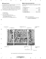
<グラフィック>, Fig.1 Charged and High Voltage Generating Point Rear View - pdp 43
 |
UPC - 012562691107
View all Pioneer 434CMX manuals
Add to My Manuals
Save this manual to your list of manuals |
Page 4 highlights
1 2 3 4 Charged Section The places where the commercial AC power is used without A passing through the power supply transformer. If the places are touched, there is a risk of electric shock. In addition, the measuring equipment can be damaged if it is connected to the GND of the charged section and the GND of the non-charged section while connecting the set directly to the commercial AC power supply. Therefore, be sure to connect the set via an insulated transformer and supply the current. 1. AC Power Cord 2. AC Inlet with Filter 3. Power Switch (S1) B 4. Fuse (In the POWER SUPPLY Unit) 5. STB Transformer and Converter Transformer (In the POWER SUPPLY Unit) 6. Other primary side of the POWER SUPPLY Unit High Voltage Generating Point The places where voltage is 100V or more except for the charged places described above. If the places are touched, there is a risk of electric shock. 1. POWER SUPPLY Unit 215V) 2. 43 X DRIVE Assy 225V to 215V) 3. 43 Y DRIVE Assy 345V) 4. 43 SCAN A Assy 345V) 5. 43 SCAN B Assy 345V) 6. X CONNECTOR AAssy 225V to 215V) 7. X CONNECTOR B Assy 225V to 215V) : Part is Charged Section. : Part is the High Voltage Generating Points other than the Charged Section. C 43 SCAN B Assy 43 Y DRIVE Assy POWER SUPPLY Unit 43 X DRIVE Assy X CONNECTOR B Assy D E 43 SCAN A Assy Power Switch (S1) AC Inlet with Filter X CONNECTOR A Assy Power Cord F Fig.1 Charged Section and High Voltage Generating Point (Rear View) 4 PDP-434CMX 1 2 3 4
-
 1
1 -
 2
2 -
 3
3 -
 4
4 -
 5
5 -
 6
6 -
 7
7 -
 8
8 -
 9
9 -
 10
10 -
11
-
12
-
13
-
14
-
15
-
16
-
17
-
18
-
19
-
20
-
21
-
22
-
23
-
24
-
25
-
26
-
27
-
28
-
29
-
30
-
31
-
32
-
33
-
34
-
35
-
36
-
37
-
38
-
39
-
40
-
41
-
42
-
43
-
44
-
45
-
46
-
47
-
48
-
49
-
50
-
51
-
52
-
53
-
54
-
55
-
56
-
57
-
58
-
59
-
60
-
61
-
62
-
63
-
64
-
65
-
66
-
67
-
68
-
69
-
70
-
71
-
72
-
73
-
74
-
75
-
76
-
77
-
78
-
79
-
80
-
81
-
82
-
83
-
84
-
85
-
86
-
87
-
88
-
89
-
90
-
91
-
92
-
93
-
94
-
95
-
96
-
97
-
98
-
99
-
100
-
101
-
102
-
103
-
104
-
105
-
106
-
107
-
108
-
109
-
110
-
111
-
112
-
113
-
114
-
115
-
116
-
117
-
118
-
119
-
120
-
121
-
122
-
123
-
124
-
125
-
126
-
127
-
128
-
129
-
130
-
131
-
132
-
133
-
134
-
135
-
136
-
137
-
138
-
139
-
140
-
141
-
142
-
143
-
144
-
145
-
146
-
147
-
148
-
149
-
150
-
151
-
152
-
153
 |
 |
