Pioneer AVHP5000DVD Other Manual - Page 1
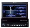
Pioneer AVHP5000DVD - DVD Player With LCD monitor Manual
 |
UPC - 012562883489
View all Pioneer AVHP5000DVD manuals
Add to My Manuals
Save this manual to your list of manuals |
Page 1 highlights
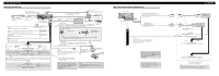
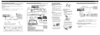
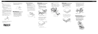
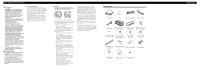
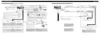
INSTALLATION MANUAL OF OF AVH-P5000DVD Printed in Thailand Imprimé en Thaïlande UC N STAR N STAR MANUEL D'INSTALLATION Connecting the Units CAUTION • PIONEER does not recommend that you install or service your display yourself. Installing or servicing the product may expose you to risk of electric shock or other hazards. Refer all installation and servicing of your display to authorized Pioneer service personnel. • Secure all wiring with cable clamps or electrical tape. Do not allow any bare wiring to remain exposed. • Do not drill a hole into the engine compartment to connect the yellow lead of the unit to the vehicle battery. Engine vibration may eventually cause the insulation to fail at the point where the wire passes from the passenger compartment into the engine compartment. Take extra care in securing the wire at this point. • It is extremely dangerous to allow the display lead to become wound around the steering column or gearshift. Be sure to install the display in such a way that it will not obstruct driving. • Make sure that wires will not interfere with moving parts of the vehicle, such as the gearshift, parking brake or seat sliding mechanism. • Do not shorten any leads. If you do, the protection circuit may fail to work properly. WARNING LIGHT GREEN LEAD AT POWER CONNECTOR IS DESIGNED TO DETECT PARKED STATUS AND MUST BE CONNECTED TO THE POWER SUPPLY SIDE OF THE PARKING BRAKE SWITCH. IMPROPER CONNECTION OR USE OF THIS LEAD MAY VIOLATE APPLICABLE LAW AND MAY RESULT IN SERIOUS INJURY OR DAMAGE. WARNING • To avoid the risk of accident and the potential vio- lation of applicable laws, the front DVD or TV (sold separately) feature should never be used while the vehicle is being driven. Also, Rear Displays should not be in a location where it is a visible distraction to the driver. • In some countries or states the viewing of images on a display inside a vehicle even by persons other than the driver may be illegal. Where such regulations apply, they must be obeyed and this unit's DVD features should not be used. Note: • This unit cannot be installed in a vehicle with- out ACC (accessory) position on the ignition switch. F ACC O F O T T ACC position No ACC position • Use this unit in other than the following conditions could result in fire or malfunction. - Vehicles with a 12-volt battery and negative grounding. - Speakers with 50 W (output value) and 4 ohm to 8 ohm (impedance value). • To prevent short-circuit, overheating or malfunction, be sure to follow the directions below. - Disconnect the negative terminal of the battery before installation. - Secure the wiring with cable clamps or adhesive tape. To protect the wiring, wrap adhesive tape around them where they lie against metal parts. - Place all cables away from moving parts, such as gear shift and seat rails. - Place all cables away from hot places, such as near the heater outlet. - Do not pass the yellow cable through a hole into the engine compartment to connect to a battery. - Cover any disconnected cable connectors with insulating tape. - Do not remove RCA caps if RCA cables are not used. - Do not shorten any cables. - Never cut the insulation of the power cable of this unit in order to share the power to other equipment. Current capacity of the cable is limited. - Use a fuse of the rating prescribed. - Never wire the speaker negative cable directly to ground. - Never band together multiple speaker's negative cables. • Control signal is output through blue/white cable when this unit is powered on. Connect it to an external power amp's system remote control or the vehicle's auto-antenna relay control terminal (max. 300 mA, 12 V DC). If the vehicle is equipped with a glass antenna, connect it to the antenna booster power supply terminal. • Never connect blue/white cable to external power amp's power terminal. Also, never connect it to the power terminal of the auto antenna. Otherwise, battery drain or malfunction may result. • IP-BUS connectors are color-coded. Be sure to connect connectors of the same color. • Black cable is ground. This cable and other product's ground cable (especially, high-current products such as power amp) must be wired separately. Otherwise, fire or malfunction may result if they are accidentally detached. Parts supplied ENGLISH This product Tuner box Power cord Antenna cable USB cable Mounting sleeve (pre-installed) Trim ring (pre-installed) Side bracket (small) (2 pcs.) (pre-installed) Screw (2 mm × 3 mm) (4 pcs.) (pre-installed) Flush surface screw (5 mm × 6 mm) (6 pcs.) (2 are pre-installed.) Binding screw (5 mm × 6 mm) (4 pcs.) Binding screw (4 mm × 3 mm) (4 pcs.) Concealing tape Side bracket (large) (2 pcs.) Rubber bush Double-ended screw Touch panel pen Holder Screw (2 mm × 5 mm) (2 pcs.)
-
 1
1 -
 2
2 -
 3
3 -
 4
4 -
 5
5 -
 6
6 -
 7
7 -
8
 |
 |