Pioneer AVHP5000DVD Other Manual - Page 4
Installation, ENGLISH - parts
 |
UPC - 012562883489
View all Pioneer AVHP5000DVD manuals
Add to My Manuals
Save this manual to your list of manuals |
Page 4 highlights
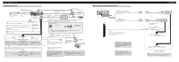
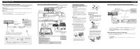
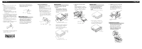
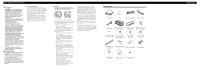
Installation Note: • Check all connections and systems before final installation. • Do not use unauthorized parts. The use of unauthorized parts may cause malfunctions. • Consult with your dealer if installation requires drilling of holes or other modifications of the vehicle. • Do not install this unit where: - it may interfere with operation of the vehicle. - it may cause injury to a passenger as a result of a sudden stop. • Do not install the display where it may (i) obstruct the driver's vision, (ii) impair the performance of any of the vehicle's operating systems or safety features, including air bags, hazard lamp buttons or (iii) impair the driver's ability to safely operate the vehicle. • The semiconductor laser will be damaged if it overheats. Install this unit away from hot places such as near the heater outlet. • Optimum performance is obtained when the unit is installed at an angle of less than 30°. • Make sure you leave enough gap between the dashboard and the LCD panel of this unit so the LCD panel can be opened and closed without contacting with the dashboard. Dashboard Leave gap LCD panel DIN Front/Rear-mount This unit can be properly installed either from "Front" (conventional DIN Front-mount) or "Rear" (DIN Rearmount installation, utilizing threaded screw holes at the sides of unit chassis). For details, refer to the following illustrated installation methods. 30° • The cords must not cover up the area shown in the figure below. This is necessary to allow the amplifires to radiate freely. Before installing the unit • Remove the trim ring and the mounting sleeve. Extend top and bottom of the trim ring outwards to remove the trim ring. And then loosen the screws (2 mm × 3 mm) to remove the mounting sleeve. • When reattaching the trim ring, push the trim ring onto the unit until it clicks after reattaching the mounting sleeve. (If the trim ring is attached upside down, the trim ring will not fit properly.) DIN Front-mount 1. Decide the position of the side brackets. • When installing in a shallow space, change the position of side brackets (small). In this case, stick concealing tape on parts that protrude from the dashboard. Mounting sleeve Screw (2 mm × 3 mm) Trim ring Concealing tape Side bracket (small) Flush surface screw (5 mm × 6 mm) • If you prefer an off-set installation in which the front panel is pushed further back, when there is a space available at the back of the unit, use the side brackets (large). 2. Install the unit into the dashboard. Insert the mounting sleeve into the dashboard. And then secure the mounting sleeve by using a screwdriver to bend the metal tabs (90°) into place. Dashboard 182 53 Rubber bush Screw Mounting sleeve Side bracket Screw (2 mm × 3 mm) DIN Rear-mount 1. Determine the appropriate position where the holes on the bracket and the side of the unit match. *1 Use binding screws (4 mm × 3 mm) only. *1 *1 • When installing in a shallow space, use the following screw holes. In this case, stick concealing tape on parts that protrude from the dashboard. *1 *1 Concealing tape Do not cover this area. Side bracket (large) Flush surface screw (5 mm × 6 mm) 2. Tighten two screws on each side. Use any of binding screws (4 mm × 3 mm), binding screws (5 mm × 6 mm) or flush surface screws (5 mm × 6 mm), depending on the shape of screw holes in the bracket. Screw Factory radio mounting bracket Dashboard or Console Fastening the front panel If you do not plan to detach the front panel, the front panel can be fastened with supplied screws and holder. • Fix the front panel to the unit using screws and holder after removing the trim ring. Screw Screw Holder ENGLISH
-
 1
1 -
 2
2 -
 3
3 -
 4
4 -
 5
5 -
 6
6 -
 7
7 -
 8
8
 |
 |
