Pioneer DEH-245 Operation Manual - Page 21
Connection, Diagram, I=E333, ougil
 |
View all Pioneer DEH-245 manuals
Add to My Manuals
Save this manual to your list of manuals |
Page 21 highlights
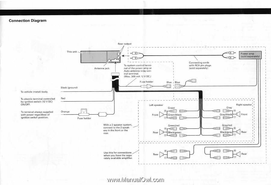
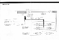
Connection Diagram Rear output To vehicle (metal) body. To electric terminal controlled by ignition switch (12 V DC) ON/OFF. To terminal always supplied with power regardless of ignition switch position. This unit Black (ground) Fr LMA / Antenna jack To system control terminal of the power amp or Auto-antenna relay control terminal. (Max. 300 mA 12 V DC.) Fuse holder I=E333 Connecting cords with RCA pin plugs (sold separately) Blue I Blue ougil • Power amp (sold separately) Red Orange Fuse holder With a 2 speaker system, connect to the 2 speak- ----- I ers in the front or the rear. Left speaker Green C), Front I Green/black mg Rear Green/red EP noi- t. :} Black/green (=-) Inc- -; WI. i I Right speaker; I Gray 1= -•1 1la (.0 I I i I Gray/black Front :I e f it ■ I Gray/red I cir. @ I Black/gray E----rau O Rear i I I I Use this for connections when you have the separately available amplifier. Rear O ODD Rear O
-
 1
1 -
2
-
3
-
4
-
5
-
6
-
7
-
8
-
9
-
10
-
11
-
12
-
13
-
14
-
15
-
 16
16 -
 17
17 -
 18
18 -
 19
19 -
 20
20 -
 21
21
 |
 |