Pioneer DJM-400 - CDJ-400 Package Operating Instructions - Page 4
Connections
 |
View all Pioneer DJM-400 - CDJ-400 Package manuals
Add to My Manuals
Save this manual to your list of manuals |
Page 4 highlights
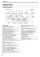
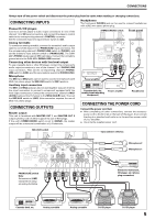
CONNECTIONS CONNECTIONS CONNECTION PANEL Rear panel 12 3 4 5 Front panel 6 18 POWER OFF ON AC IN MONO 1 MASTER OUT L R STEREO 2 MIC2 AUX(R) MIC MIC1 AUX(L) AUX PHONO LINE CD PHONO LINE L LINE PHONO R L LINE PHONO R CONTROL CD SIGNAL GND CONTROL 17 16 15 14 13 12 11 10 9 8 7 1. POWER switch 2. STEREO/MONO selector switch When switch is set to the [MONO] position, master output is in monaural. 3. MIC2/AUX(R) input connector Ø6.3 mm phone-type input connector. Use for microphone input, or for right (R) channel of component with line level output. 4. MIC/AUX input selector switch When this switch is set to [AUX], the MIC1 and MIC2 input connectors function as AUX (L) and AUX (R) input connectors. 5. MIC1/AUX(L) input connector Ø6.3 mm phone-type input connector. Use for microphone input, or for left (L) channel of component with line level output. 6. Signal grounding terminal (SIGNAL GND) Use to connect ground wires from analog players. This is not a safety grounding terminal. 7. Channel 1 CONTROL connector Ø3.5 mm mini-phone type connector. Connect to control connector of the DJ CD player connected to channel 1 inputs. When this connection is made, the DJ mixer's fader lever can be used to perform fader start play and back cue on the channel 1 DJ CD player. 8. Channel 1 CD input connectors (CD) RCA type line level input connectors. Use to connect a DJ CD player or other component with line level output. 9. Channel 1 PHONO/LINE input connectors RCA type phono level (for MM cartridge) or line level input connectors. Select function using channel 1 PHONO/LINE selector switch. 10. Channel 1 PHONO/LINE selector switch Use to select function of channel 1 PHONO/LINE input connectors. 11. Channel 2 CONTROL connector Ø3.5 mm mini-phone type connector. Connect to control connector of the DJ CD player connected to channel 2 inputs. When this connection is made, the DJ mixer's fader lever can be used to perform fader start play and back cue on the channel 2 DJ CD player. 12. Channel 2 CD input connectors (CD) RCA type line level input connectors. Use to connect a DJ CD player or other component with line level output. 13. Channel 2 PHONO/LINE input connectors RCA type phono level (for MM cartridge) or line level input connectors. Select function using channel 2 PHONO/LINE selector switch. 14. Channel 2 PHONO/LINE selector switch Use to select function of channel 2 PHONO/LINE input connectors. 15. MASTER OUT 2 output connectors RCA type unbalanced output. 16. MASTER OUT 1 output connectors RCA type unbalanced output. 17. Power inlet (AC IN) Use the accessory power cord to connect to an AC power outlet of the proper voltage. 18. Headphones jack (PHONES) Use to connect stereo headphones equipped with Ø6.3 mm stereo headphones plug. 4
-
 1
1 -
 2
2 -
 3
3 -
 4
4 -
 5
5 -
 6
6 -
 7
7 -
 8
8 -
 9
9 -
 10
10 -
11
-
12
-
13
-
14
-
15
-
16
 |
 |
