Pioneer DJM-400 - CDJ-400 Package Operating Instructions - Page 5
Connecting Inputs, Connecting Outputs, Connecting The Power Cord
 |
View all Pioneer DJM-400 - CDJ-400 Package manuals
Add to My Manuals
Save this manual to your list of manuals |
Page 5 highlights
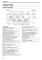
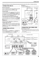
CONNECTIONS Always turn off the power switch and disconnect the power plug from its outlet when making or changing connections. CONNECTING INPUTS Pioneer DJ CD players Connect a DJ CD player's audio output connectors to one of the channel 1 to 2 CD input connectors, and connect the player's control cable to the corresponding channel's CONTROL connector. Set the connected channel's input selector switch to [CD]. Analog turntable To connect an analog turntable, connect the turntable's audio output cable to one of the channel 1 to 2 PHONO/LINE input connectors. Set the corresponding channel's PHONO/LINE switch to [PHONO], and set the channel's input selector switch to [PHONO/LINE]. The DJM400's PHONO inputs support MM cartridges. Connect the turntable's ground wire to the DJM-400's SIGNAL GND terminal. Connecting other devices with line level output To use a cassette deck or other CD player, connect the component's audio output connectors to one of the channel 1 to 2 PHONO/LINE input connectors. Then set the corresponding channel's PHONO/ LINE switch to [LINE], and the input selector switch to [PHONO/LINE]. Microphone The MIC1 and MIC2 jacks can be used to connect microphones with Ø6.3 mm phone plugs. Set MIC/AUX switch to [MIC] position. Auxiliary input connectors The MIC1 and MIC2 jacks can also be used together as a pair of stereo line input connectors to connect a component equipped with line level output connectors. Connect the component's L channel to MIC1 (AUX(L)) jack and the R channel to the MIC2 (AUX(R)) jack. Then set the MIC/AUX switch to [AUX] (this connection requires the use of Ø6.3 mm phone plugs). CONNECTING OUTPUTS Master output This unit is furnished with MASTER OUT 1 and MASTER OUT 2 output systems, both of which support the use of RCA plugs. If the unit's STEREO/MONO switch is set to [MONO], the master output will be a monaural combination of L+R channels. Headphones The front panel PHONES jack can be used to connect headphones with a Ø6.3 mm stereo phone plug. STEREO/MONO switch Front panel POWER OFF ON AC IN MONO STEREO 1 2 MASTER OUT L R LR RL Power amplifier Cassette deck, etc. (analog input recording component) Power amplfier Headphones CONNECTING THE POWER CORD Connect the power cord last. ÷ After completing all other connections, connect the accessory power cord to the AC inlet on the back of the player, then connect the plug to a standard wall outlet or to the auxiliary power outlet of your amplifier. ÷ Use only the supplied power cord. MIC/AUX switch Input selector switches POWER OFF ON AC IN MONO 1 MASTER OUT L R STEREO 2 MIC2 AUX(R) MIC MIC1 AUX(L) AUX PHONO LINE CD PHONO LINE L LINE PHONO R L LINE PHONO R CONTROL CD SIGNAL GND CONTROL PHONO/LINE switch Note: Set switch to [LINE] except when using an analog turntable LR RL RL RL RL Microphone 2 Microphone 1 R L Electronic instrument, CD player, etc. (phone plug connection) Cassette deck, etc. Analog turntable Analog turntable DJ CD player DJ CD player 5
-
 1
1 -
 2
2 -
 3
3 -
 4
4 -
 5
5 -
 6
6 -
 7
7 -
 8
8 -
 9
9 -
 10
10 -
 11
11 -
12
-
13
-
14
-
15
-
16
 |
 |
