Poulan 1994-01 User Manual - Page 6
Assembly
 |
View all Poulan 1994-01 manuals
Add to My Manuals
Save this manual to your list of manuals |
Page 6 highlights
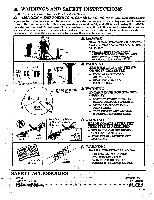
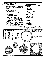
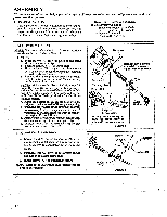
ASSEMBLY (If tool is received assembled, repeat all steps in this section to be sure assembly is correct and is adjusted for the operator.) A. PREPARATION This Operator's Manual is designed to help you assemble the tool and to provide its safe operation. It is important that you read the entire manual to become familiar with the tool before you begin assembly. 1. Read your Operator's Manual 2. Tools you will need: - Small Hex Wrench (provided) - Large Hex Wrench (provided) - Adjustable Wrench - Standard Screwdriver B.ASSEMBLY STEPS NOTE: Hardware referred to in the followingsections are shown in actual size in Figure 1. 1. TUBE a. Place screws "A" into the holes on the front shroud as shown in Figure 2 . b. Position locknuts "D." in lower holes. c. Hold locknuts "D." in place; tighten screws with small hex wrench (provided) just enough to hold hardware together. d. Remove the packing cover from the straight end of the tube if so equipped. Your unit may not have a packing cover. NOTE: Make sure the drive shaft does not fall out of the tube. Dirt on the shaft willsignificantly ___-reducethelife-ofthe-unitrlf-the-drive-shaftfalls----out of the tube, clean, re-lubricate, and re-install. See "Drive Shaft Lubrication" in the Maintenance section. e. Align the bottom groove on the tube with the ridge on the lower wall of the engine opening. f. Turn the arbor shaft at the bottom of the tube as necessaryto alignthesquare end oftheshaft with thesquare holeinsidethefront openingof the engine. Figure 2 (inset). Firmlypush tube into the engine openinguntil the nose cone contacts the foam grip. Figure 2 h. Tighten screws "A." alternately with the hex wrench until secure. Figure 2 . 2. HANDLEBAR ASSEMBLY a. Locate the decal on the handlebar. Align the mounting block between the arrows on the decal; then, seat the handlebar in the mounting block. b. Position cover "I." between the arrows on the handlebar and align screw holes. c. insert screws "C." and tighten securely. NOTE:Refer to theillustration on the front coverfor proper positioning. Screws A. Remove any packing ie./ . material that may be on the end of the tube. Lockouts D. Close up view Luc Shaft Foam Grip Ridge and bottom groove It may be zwe.aqsary to turn the arbor shaft to alignwiththesquarehole. Figure 2 Tube Arbor Shaft Screw C.---*/ Cover L / Mounting Block Figure 3 Handlebar
-
 1
1 -
 2
2 -
 3
3 -
 4
4 -
 5
5 -
 6
6 -
 7
7 -
 8
8 -
 9
9 -
 10
10 -
 11
11 -
 12
12 -
13
-
14
-
15
-
16
-
17
-
18
-
19
-
20
-
21
-
22
-
23
-
24
 |
 |
