Poulan 1994-01 User Manual - Page 7
Poulan 1994-01 Manual
 |
View all Poulan 1994-01 manuals
Add to My Manuals
Save this manual to your list of manuals |
Page 7 highlights
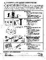
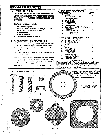
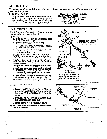
3. THROTTLE HANDLE ASSEMBLY a. Remove the rear screw from the trigger housing. Figure 4 . b. Slide the trigger housing onto the right side of the handlebar. Align screw holes in the trigger housing with the screw hole in the handlebar c. Reinstall the rear screw in the trigger housing. Tighten securely. NOTE:Make sure the engine switch is located on the top side of the handle. d. Secure the loose wire assembly in the groove in the shaft pad. Screw Screw Wire Assembly Hole In Shaft Pad Figure 4 4. TRIMMER HEAD & PLASTIC SHIELD A WARNING The shield must be properly installed for all line trimmer usage. The shield provides partial protectionfrom the risk of thrown objects to the operator and others and is equipped with a line limiter which cuts excess line to proper length- A WARNING Failure to install the shield in the position shown in Figure 5 can result in serious injury to the operator. The length of the shield must be aligned with the length of the tube. Direct the widest imartof the-shield tea:Tad-the engine a. Remove and discard the parking cover from the arbor shaft if so equipped. CATMON: I Theline limiter (on the underside of the shield) is sharp and can cut you. b. Place the shield under the gear box and insert four screws "B." through the gear box into the shield. Figure 5 . c. Tightenscrews"B." evenlyandsecurelywitha standard screwdriver. NOTE: Although ascrewdriverslot isprovided in screws "B.", it is easier to install the screws with a wrench or socket. d. Install grass washer "H." over the arbor shaft. Make sure grass washer "H." is against and curved over the dust cup. Figure 5 . e. Start threading the trimmer head onto the arbor shaft as shown in Figure 5 . f. Align the hole in the dust cup with the hole in the center front of the gear box by turning the trimmer head. g. Insert thelarge hexwrench (provided)into the aligned holes to keep the arbor shaft from turning. Figure 5 (inset). 5. METAL SHIELD AND BLADE A DANGER The metal shield must be properly installed on the tool anytime the tool is used with the blade. The forward lip on the metal shield helps to reduce the occurrence of blade thrust which can cause serious injury such as amputation to the operator or bystanders. A DANGER Failure to install the shield in the position shown in Figures 6 and 7 can result in serious injury to the operator. The length of the shield must be aligned with the length of the tube. Direct widest part of the shield toward the engine. Gear Box Clamp Widest Part of Shield Toward Engine Screw B. Dust Cup Arbor Shaft Line Limiter 46) Hex Wrench Grass -H. Trimmer Head Direction to Install Figure 5 h. Tighten the trimmer head counterclockwise against grass washer "H." and the dust cup while holding the large hex wrench. See Figure 5 (inset). i. Remove the hex wrench. NOTE: To remove the trimmer head, insert the hex wrench into the aligned holes in the dust cup and gear box. Unthread the trimmer head. Be sure to store the grass washer, plastic shield, 4 shield screws, and hardware with the trimmer head for future use. NOTE: Ifyour unit isequipped asalinetrimmer,remove the trimmer head, grass washer, and plastic shield before installingthe metal shield and blade. Store parts for future use. a. Remove and discard the parking cover from the arbor shaft, if so equipped. b. Remove the dust cup. c. Position the retention plate on the underside ofthemetalshieldandalignscrewholes. Make suretheflat sideoftheplate isagainstthe metal shielcL Figure 6 . d. Hold theretention plate in position and piece the metal shield under the gear box. Align screw holes. Figure 6 .
-
 1
1 -
 2
2 -
 3
3 -
 4
4 -
 5
5 -
 6
6 -
 7
7 -
 8
8 -
 9
9 -
 10
10 -
 11
11 -
 12
12 -
13
-
14
-
15
-
16
-
17
-
18
-
19
-
20
-
21
-
22
-
23
-
24
 |
 |
