Poulan 1994-01 User Manual - Page 8
Poulan 1994-01 Manual
 |
View all Poulan 1994-01 manuals
Add to My Manuals
Save this manual to your list of manuals |
Page 8 highlights
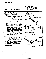
e. Insert the four shield screws "C." one at a time through the gear box and shield, then thread them into retention plate "J.". f. Tighten the screws evenly and securely with the 3/16" hex wrench (provided). g. Install the dust cup over the arbor shaft. h. Install blade over arbor shaft, making sure the hole in the center of the blade is fitted around the raised center on the dust cup. Figure 6 . NOTE: When installing blade, make sure teeth on blade are oriented as shown in Figure 6 i. Install the large flat washer "G.", cupped washer "H.", and nut "E." as shown in Figure 6 . Besure cupped washer "H."is installed as shown in Figure 6 (inset). j. Align hole in the dust cup with the hole in the side of the gear box by turning the dust cup. k. Insert the large hex wrench (provided) into the aligned holes. Figure 6 (inset, upper left). 1. While holding the hex wrench in position, firmly tighten nut "E." counterclockwise with a wrench. m. Remove the hex wrench. n. Turn blade by hand. If the blade binds against shield, blade is not centered. Reinstall blade. NOTE: lb remove the blade, align holes as in step "j."; then, insert the large hex wrench. Unthread hex flange nut and remove parts. Be sure to store the blade, flat washer, cupped -- washm;and Mange nuTor future use. Ing Hex Wrench in aligned holes V Screw C.* Gear Bqx Clamp Widest Portion of Shield* Toward Engine Rpieat:enjt.i.on- Dust Cup ar ey7 Blade* I ...''' o , CTuBoplraadceii:dSide Washer H.* r.,./ Washer G.* C-rd Washer H.* (see inset) ;**se-e- Nut E.* Figure 6 A WARNING Parts ntsted-wifire-aratritiealmid must be supplied by your POULAN PRO dealer. Failure to use proper parts can cause the blade to fly off and seriously hurt you or others. 6. SHOULDER STRAP A WARNING Proper shoulder strap and handlebar adjustments before starting the engine are required for safe and efficient use. a Try on shoulder strap and adjust for fit and balance before starting the engine and beginning a cutting operation. b. Insert your right arm and head through the shoulder strap and allow it to rest on your left shoulder. Makesure the dangersign is onyour back and the hook is to the right side of your waist. Figure 7 . NOTE: A one-half twist is built in the shoulder straptoallowthestrap to rest flat on theshoulder. c. Adjust the strap so that the hook will be about 10 inches below the waist when the hook is attached to the shoulder strap. d. Fasten shoulder strap hook to clamp and lift tool to the operating position. Figure 7. e. Check for the following: 1. Left arm extended, hand holding handlebar griP• 2. Right hand holdingtriggerhandle,fingerson throttle trigger. 3. Engine below waist level. 4. Shoulder strap pad centered on left shoulder. 5. Danger sign centered on your back. 6. Full weight of tool on left shoulder. 7. Without operator bending over, the blade or trimmer head is near and parallel to the ground and easilycontactsmaterial tobecut. f. Modify these initial adjustments as necessary for comfort and control but do not locate the handlebar mounting block below the point of thearrowon thesafetylabels.Do not locatethe shoulder strap clamp in any position other than between the engine and handlebar mounting block. OPERATING . POSITION Danger Sign Centered on Your Bark a Figure 7
-
 1
1 -
2
-
 3
3 -
 4
4 -
 5
5 -
 6
6 -
 7
7 -
 8
8 -
 9
9 -
 10
10 -
 11
11 -
 12
12 -
 13
13 -
14
-
15
-
16
-
17
-
18
-
19
-
20
-
21
-
22
-
23
-
24
 |
 |
