ProForm 325 Cse Elliptical Uk Manual - Page 7
Do not remove the wire ties B, C, and the Bolt yet.
 |
View all ProForm 325 Cse Elliptical manuals
Add to My Manuals
Save this manual to your list of manuals |
Page 7 highlights
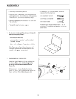
3. Orient the Rear Stabilizer (9) as indicated by the sticker. 3 While a second person lifts the rear of the Frame (1), attach the Rear Stabilizer (9) to the Frame with two M10 x 68mm Screws (34). 9 34 4. Orient the Upright (2) and the Top Shield (41) as shown. Slide the Top Shield upward onto the 4 Upright. Do not remove the wire ties (B, C) from the Upright. Next, slide the Upright (2) onto the Frame (1). Attach the Upright (2) with four M10 x 20mm Screws (40), an M10 x 74mm Bolt (7), and an M10 Locknut (33); do not tighten the Screws and the Bolt yet. 1 C B B 2 41 40 40 7 33 40 1 7
-
 1
1 -
 2
2 -
 3
3 -
 4
4 -
 5
5 -
 6
6 -
 7
7 -
 8
8 -
 9
9 -
 10
10 -
 11
11 -
 12
12 -
13
-
14
-
15
-
16
-
17
-
18
-
19
-
20
-
21
-
22
-
23
-
24
-
25
-
26
-
27
-
28
-
29
-
30
-
31
-
32
 |
 |

7
3.
Orient the Rear Stabilizer (9) as indicated by the
sticker.
While a second person lifts the rear of the Frame
(1), attach the Rear Stabilizer (9) to the Frame
with two M10 x 68mm Screws (34).
34
9
1
3
4
4.
Orient the Upright (2) and the Top Shield (41)
as shown. Slide the Top Shield upward onto the
Upright.
Do not remove the wire ties (B, C)
from the Upright.
Next, slide the Upright (2) onto the Frame (1).
Attach the Upright (2) with four M10 x 20mm
Screws (40), an M10 x 74mm Bolt (7), and an
M10 Locknut (33);
do not tighten the Screws
and the Bolt yet.
2
41
B
B
C
33
7
1
40
40
40