ProForm 505 Cst Treadmill English Manual - Page 12
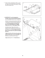
Attach the Left Upright Cover 80 to the Left - key
 |
View all ProForm 505 Cst Treadmill manuals
Add to My Manuals
Save this manual to your list of manuals |
Page 12 highlights
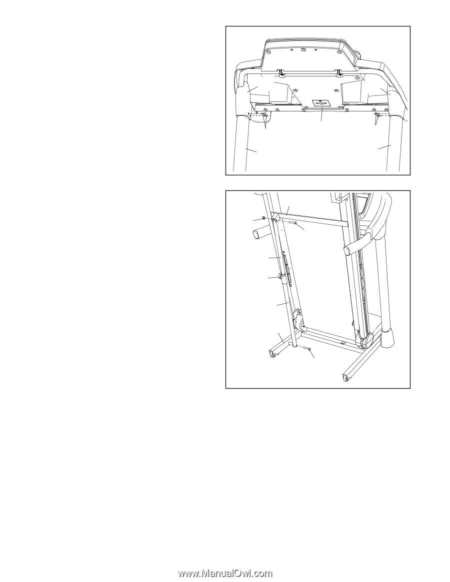
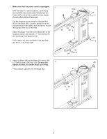
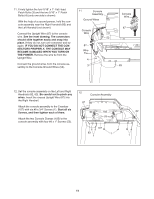
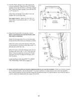
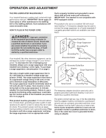
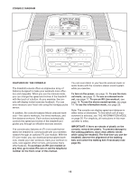
13. Hold the Right Upright Cover (86) against the console assembly. Align the holes in the Right 13 Upright Cover with the holes in the Right Upright (85). Attach the Right Upright Cover with two #8 x 3/4" Screws (1). Attach the Left Upright Cover (80) to the Left 86 Upright (84) in the same way. See steps 4 and 6. Tighten the four 3/8" x 4" Patch Bolts (7) and the two 3/8" x 1 1/2" Patch Bolts (14). 1 85 80 Console Assembly 1 84 14. Raise the Frame (55) to the position shown. Have a second person hold the Frame until this step is completed. Orient the Storage Latch (51) so that the large barrel and the latch knob are oriented as shown. Attach the upper end of the Storage Latch (51) to the bracket on the Frame (55) with a 3/8" x 2" Bolt (8) and a 3/8" Nut (10). Attach the lower end of the Storage Latch (51) to the Base (95) with a 3/8" x 1 3/4" Patch Bolt (6). Note: It may be necessary to move the Frame (55) back and forth to align the Storage Latch with the Base. Lower the Frame (55) (see HOW TO LOWER THE TREADMILL FOR USE on page 21). 14 10 55 8 51 Latch Knob Large Barrel 95 6 15. Make sure that all parts are properly tightened before you use the treadmill. If there are sheets of plastic on the treadmill decals, remove the plastic. To protect the floor or carpet, place a mat under the treadmill. Note: Extra hardware may be included. Keep the included hex keys in a secure place; one of the hex keys is used to adjust the walking belt (see pages 23 and 24). 12
-
 1
1 -
2
-
3
-
4
-
5
-
6
-
 7
7 -
 8
8 -
 9
9 -
 10
10 -
 11
11 -
 12
12 -
 13
13 -
 14
14 -
 15
15 -
 16
16 -
 17
17 -
18
-
19
-
20
-
21
-
22
-
23
-
24
-
25
-
26
-
27
-
28
-
29
-
30
-
31
-
32
 |
 |