ProForm 645 Treadmill English Manual - Page 9
Aged When The Power Is Turned On.
 |
View all ProForm 645 Treadmill manuals
Add to My Manuals
Save this manual to your list of manuals |
Page 9 highlights
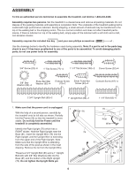
8. While a second person holds the console assembly near the Pulse Bar (66), connect the Ground Wire (107) on the Pulse Bar to the ground wire from the console assembly. Connect the wire from the console assembly to the Upright Wire (75). Make sure to connect the connectors properly (see the inset drawing). The connectors should slide together easily and snap into place. If the connectors do not slide together easily and snap into place, turn one connector and then try again. IF THE CONNECTORS ARE NOT CONNECTED PROPERLY, THE CONSOLE MAY BE DAMAGED WHEN THE POWER IS TURNED ON. Lay the wires inside the bottom of the Pulse Bar (66). 9. Set the console assembly on the Left and Right Uprights (70, 76). Be careful not to pinch any wires. Attach the console assembly to the Pulse Bar (66) with six 3/4" Screws (23). Start all six Screws, before tighten them yet. 8 Console Assembly Ground 75 Wire 107 66 Wire 75 76 9 Console Assembly 66 23 23 23 76 70 10.Identify the Left Handrail Cover (68), which has a LEFT sticker on it. Slide the Left Handrail Cover onto the left Handrail (62) and up against the console assembly. Tighten two Cover Screws (52) into the Left Handrail Cover and the Left Upright (70); be careful not to overtighten the Cover Screws. 10 Console Assembly 68 62 Attach the Right Handrail Cover (74) in the same way. 52 70 74 62 52 76 9
-
 1
1 -
2
-
3
-
 4
4 -
 5
5 -
 6
6 -
 7
7 -
 8
8 -
 9
9 -
 10
10 -
 11
11 -
 12
12 -
 13
13 -
 14
14 -
15
-
16
-
17
-
18
-
19
-
20
-
21
-
22
-
23
-
24
-
25
-
26
-
27
-
28
-
29
-
30
-
31
-
32
 |
 |
