ProForm 8.0 Zt Treadmill English Manual - Page 8
x 68mm Patch Bolt 114, and M10 Star
 |
View all ProForm 8.0 Zt Treadmill manuals
Add to My Manuals
Save this manual to your list of manuals |
Page 8 highlights
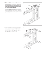
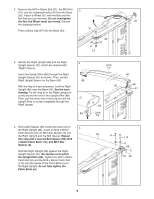
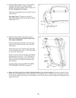
3. Remove the M10 x 50mm Bolt (31), the M10 Nut 3 (19), and the shipping bracket (A) from the Base (95). Attach a Wheel (97) with the Bolt and the Nut that you just removed. Do not overtighten the Nut; the Wheel must turn freely. Discard 87 the shipping bracket. 31 Press a Base Cap (87) into the Base (95). 95 97 A 19 4. Identify the Right Upright (89) and the Right Upright Spacer (91), which are marked with "Right" stickers. Insert the Upright Wire (88) through the Right Upright Spacer (91) as shown. Then, set the Right Upright Spacer on the Base (95). With the help of a second person, hold the Right Upright (89) near the Base (95). See the inset drawing. Tie the long tie in the Right Upright securely around the end of the Upright Wire (88). Then, pull the other end of the long tie until the Upright Wire is routed completely through the Right Upright. 4 88 88 Long Tie 95 89 88 91 89 Long Tie 5. Hold a Bolt Spacer (90) inside the lower end of the Right Upright (89). Insert an M10 x 95mm 5 Patch Bolt (8) with an M10 Star Washer (9) into the Right Upright and the Bolt Spacer. Repeat this step with a second Bolt Spacer (90), M10 x 68mm Patch Bolt (114), and M10 Star Washer (9). Hold the Right Upright (89) against the Right Upright Spacer (91). Be careful not to pinch the Upright Wire (88). Tighten the M10 x 95mm Patch Bolt (8) and the M10 x 68mm Patch Bolt (114) until the heads of the Patch Bolts touch the Right Upright; do not fully tighten the Patch Bolts yet. 89 8 114 9 88 91 90 8
-
 1
1 -
2
-
 3
3 -
 4
4 -
 5
5 -
 6
6 -
 7
7 -
 8
8 -
 9
9 -
 10
10 -
 11
11 -
 12
12 -
 13
13 -
14
-
15
-
16
-
17
-
18
-
19
-
20
-
21
-
22
-
23
-
24
-
25
-
26
-
27
-
28
-
29
-
30
-
31
-
32
 |
 |
