ProForm C 630 Elliptical English Manual - Page 11
Maintenance And Troubleshooting - parts
 |
View all ProForm C 630 Elliptical manuals
Add to My Manuals
Save this manual to your list of manuals |
Page 11 highlights
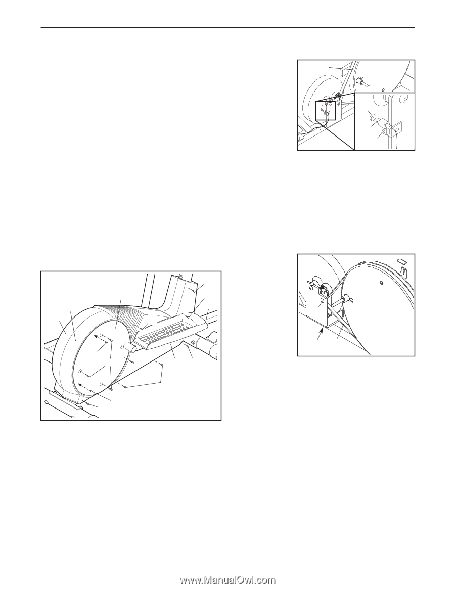
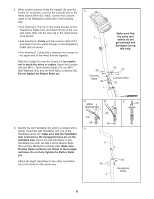
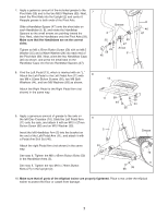
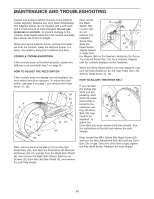
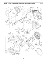
MAINTENANCE AND TROUBLESHOOTING Inspect and properly tighten all parts of the elliptical trainer regularly. Replace any worn parts immediately. The elliptical trainer can be cleaned with a soft cloth and a small amount of mild detergent. Do not use abrasives or solvents. To prevent damage to the console, keep liquids away from the console and keep the console out of direct sunlight. When storing the elliptical trainer, remove the batteries from the console. Keep the elliptical trainer in a clean, dry location, away from moisture and dust. CONSOLE TROUBLESHOOTING If the console does not function properly, replace the batteries (see assembly step 3 on page 5). HOW TO ADJUST THE REED SWITCH If the console does not display correct feedback, the reed switch should be adjusted. To adjust the reed switch, see step 9 on page 7 and remove the Pedal Arms (11, 12). 64 15 52 4 12 3 64 67 51 67 64 14 64 52 Next, remove the four Screws (51) from the right Pedal Disc (15), and slide the Pedal Disc off. Remove all Screws (52, 67, and 64) from the Right Side Shield (4), and remove the Right Side Shield. Remove all Screws (52) from the Left Side Shield (3), and remove the Left Side Shield. Next, locate the Reed 15 Switch (53). Loosen, but do not remove, the 58 indicated Screw (52). Slide the 53 Reed Switch 52 slightly toward or away from the Magnet (58) on the flywheel. Retighten the Screw. Turn the left Pedal Disc (15) for a moment. Repeat until the console displays correct feedback. When the Reed Switch (53) is correctly adjusted, reattach the Side Shields (3, 4), the right Pedal Disc (15), and the Pedal Arms (11, 12). HOW TO ADJUST THE DRIVE BELT If you can feel the pedals slip while you are pedaling, even when the resis- tance knob is turned to the 26 maximum set- ting, the Drive Belt (19) may need to be 62 19 adjusted. To adjust the Drive Belt, you must remove both side shields. See the instructions at the left and remove the side shields. Next, loosen the M8 x 22mm Flat Head Screw (26) and turn the Idler Adjustment Bolt (62) until the Drive Belt (19) is tight. Once the Drive Belt is tight, tighten the Flat Head Screw. Reattach the side shields. 11
-
 1
1 -
2
-
3
-
4
-
5
-
 6
6 -
 7
7 -
 8
8 -
 9
9 -
 10
10 -
 11
11 -
 12
12 -
 13
13 -
 14
14 -
 15
15 -
 16
16
 |
 |