ProForm C 630 Elliptical English Manual - Page 5
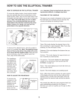
The Console 23 requires three 1.5 V AA batteries
 |
View all ProForm C 630 Elliptical manuals
Add to My Manuals
Save this manual to your list of manuals |
Page 5 highlights
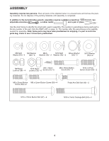
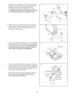
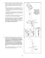
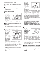
1. Identify the Front Stabilizer (10). While another person lifts the front of the Frame (1), attach the Front Stabilizer to the Frame with two M10 x 75mm Carriage Bolts (34) and two M10 Nylon Locknuts (33). Make sure that the Front Stabilizer is turned so the Wheels (22) are not touching the floor. 1 22 22 10 2. While another person lifts the back of the Frame (1) 2 slightly, attach the Rear Stabilizer (9) to the Frame with two M10 x 75mm Carriage Bolts (34) and two M10 Nylon Locknuts (33). 34 33 1 3. The Console (23) requires three 1.5 V "AA" batteries; alkaline batteries are recommended. Insert three batteries into the battery compartment. Make sure that the batteries are oriented as shown by the diagram inside of the battery compartment. 3 23 1 33 33 9 34 Batteries 4. Hold the Console (23) near the Upright (2). Insert the 4 console cable and the console wire down through the Upright. Next, connect the ground wire to the Upright with an M4 x 16mm Screw (52) as indicated. Insert the excess wire into the Upright. Attach the Console (23) to the Upright (2) with four M4 x 16mm Screws (52). Be careful to avoid pinching the wires and cable. 23 Ground Wire 52 52 Console Wire Console Cable 52 2 5
-
 1
1 -
 2
2 -
 3
3 -
 4
4 -
 5
5 -
 6
6 -
 7
7 -
 8
8 -
 9
9 -
 10
10 -
 11
11 -
12
-
13
-
14
-
15
-
16
 |
 |
