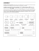
ProForm C 630 Elliptical English Manual - Page 6
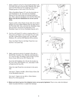
make sure that the Handlebar
 |
View all ProForm C 630 Elliptical manuals
Add to My Manuals
Save this manual to your list of manuals |
Page 6 highlights
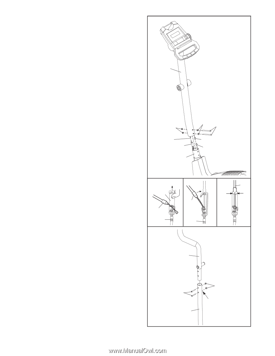
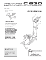
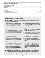
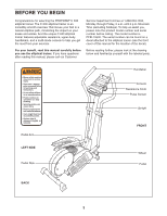
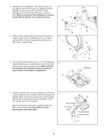
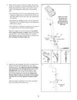
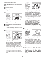
5. While another person holds the Upright (2) near the Frame (1) as shown, connect the console wire to the Reed Switch Wire (53). Next, connect the console cable to the Resistance Cable (65) in the following way: • See drawing A. Pull up on the metal bracket on the Resistance Cable (65), and insert the tip of the console cable (CC) into the wire clip in the metal bracket as shown. • See drawing B. Firmly pull the console cable (CC) and slide it into the metal bracket on the Resistance Cable (65) as shown. • See drawing C. Using pliers, squeeze the prongs on the upper end of the metal bracket together. Slide the Upright (2) onto the Frame (1); be careful not to pinch the wires or cables. Attach the Upright with two M10 x 76mm Button Bolts (27), two M10 Split Washers (43), and two M10 Nylon Locknuts (33). Do not tighten the Button Bolts yet. 5 2 33 Console Cable 65 1 Make sure that the wires and cables do not get pinched and damaged during this step. 43 27 Console Wire 53 6. Identify the Left Handlebar (6), which is marked with a sticker. Insert the Left Handlebar into one of the Handlebar Arms (5); make sure that the Handlebar Arm is turned so the hexagonal holes are on the indicated side. Attach the Left Handlebar to the Handlebar Arm with two M8 x 45mm Button Bolts (50) and two M8 Nylon Locknuts (38). Make sure that the Nylon Locknuts are inside of the hexagonal holes. Do not fully tighten the Button Bolts yet. Attach the Right Handlebar to the other Handlebar Arm (not shown) in the same way. A Metal Bracket CC 65 6 B CC 65 6 50 5 C CC 38 Hexagonal Holes 6
-
 1
1 -
 2
2 -
 3
3 -
 4
4 -
 5
5 -
 6
6 -
 7
7 -
 8
8 -
 9
9 -
 10
10 -
 11
11 -
 12
12 -
13
-
14
-
15
-
16
 |
 |