ProForm Power 575i Instruction Manual - Page 13
When You Turn On The Power.
 |
View all ProForm Power 575i manuals
Add to My Manuals
Save this manual to your list of manuals |
Page 13 highlights
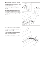
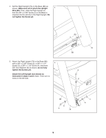
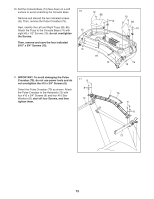
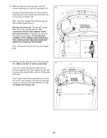
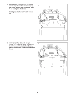
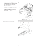
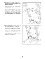
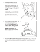
12. With the help of a second person, hold the console assembly (H) near the Handrails (72). Connect the ground wire (I) from the console assembly (H) to the Console Ground Wire (76) on the Pulse Crossbar (75). Next, insert the Upright Wire (80) through the two indicated looped ties (J). See the inset drawing. Connect the Upright Wire (80) to the console wire (K). The connectors should slide together easily and snap into place. If they do not, turn one connector and try again. IF YOU DO NOT CONNECT THE CONNECTORS PROPERLY, THE CONSOLE MAY BECOME DAMAGED WHEN YOU TURN ON THE POWER. Then, remove the wire tie (A) from the Upright Wire. 12 H J 80 72 A K 76 I 75 K 80 13. Set the console assembly (H) on the Handrails (72). Make sure that no wires are pinched. Insert the excess Upright Wire (80) into the console assembly (H). Next, tighten the two ties (J) around the Upright Wire, and cut off the ends of the ties. Then, attach the console assembly (H) with the four 5/16" x 3/4" Screws (13) that you removed in step 10 and four 5/16" Star Washers (7); do not tighten the Screws yet. 13 H 80 72 J 7 13 72 7 13 13
-
 1
1 -
2
-
3
-
4
-
5
-
6
-
7
-
 8
8 -
 9
9 -
 10
10 -
 11
11 -
 12
12 -
 13
13 -
 14
14 -
 15
15 -
 16
16 -
 17
17 -
 18
18 -
19
-
20
-
21
-
22
-
23
-
24
-
25
-
26
-
27
-
28
-
29
-
30
-
31
-
32
-
33
-
34
-
35
-
36
-
37
-
38
-
39
-
40
 |
 |
