ProForm Power 575i Instruction Manual - Page 17
IMPORTANT: The Tablet Holder 26 is
 |
View all ProForm Power 575i manuals
Add to My Manuals
Save this manual to your list of manuals |
Page 17 highlights
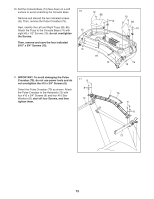
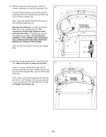
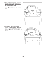
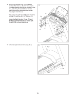
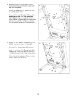
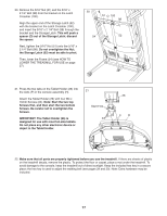
20. Remove the 5/16" Nut (51) and the 5/16" x 2 1/4" Bolt (98) from the bracket on the Latch Crossbar (100). Align the upper end of the Storage Latch (52) with the bracket on the Latch Crossbar (100), and insert the 5/16" x 2 1/4" Bolt (98) through the bracket and the Storage Latch. This will push a spacer (O) out of the Storage Latch; discard the spacer. Next, tighten the 5/16" Nut (51) onto the 5/16" x 2 1/4" Bolt (98). Do not overtighten the Nut; the Storage Latch (52) must be able to pivot. Then, lower the Frame (54) (see HOW TO LOWER THE TREADMILL FOR USE on page 27). 20 51 O 100 98 54 52 21. Press the two tabs on the Tablet Holder (26) into the slots (P) in the console assembly (H). Attach the Tablet Holder (26) with four M4 x 16mm Screws (24). Note: Start the two top Screws first, and then start the two bottom Screws. Be careful not to overtighten the Screws. IMPORTANT: The Tablet Holder (26) is designed for use with most full-size tablets. Do not place any other electronic device or object in the Tablet Holder. 21 Start First 24 26 P H 22. Make sure that all parts are properly tightened before you use the treadmill. If there are sheets of plastic on the treadmill decals, remove the plastic. To protect the floor or carpet, place a mat under the treadmill. To avoid damage to the console, keep the treadmill out of direct sunlight. Keep the included hex key in a secure place; the hex key is used to adjust the walking belt (see pages 29 and 30). Note: Extra hardware may be included. 17
-
 1
1 -
2
-
3
-
4
-
5
-
6
-
7
-
8
-
9
-
10
-
11
-
 12
12 -
 13
13 -
 14
14 -
 15
15 -
 16
16 -
 17
17 -
 18
18 -
 19
19 -
 20
20 -
 21
21 -
 22
22 -
23
-
24
-
25
-
26
-
27
-
28
-
29
-
30
-
31
-
32
-
33
-
34
-
35
-
36
-
37
-
38
-
39
-
40
 |
 |
