ProForm Space Saver 500 Treadmill English Manual - Page 7
Attach a Hub Cover 75 to the Left Crank Arm
 |
View all ProForm Space Saver 500 Treadmill manuals
Add to My Manuals
Save this manual to your list of manuals |
Page 7 highlights
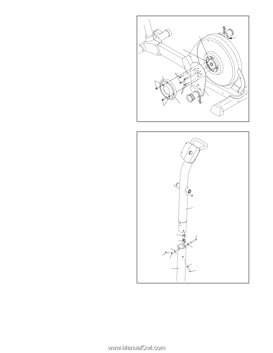
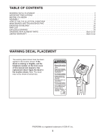
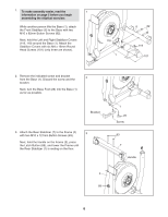
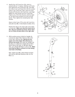
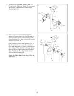
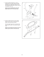
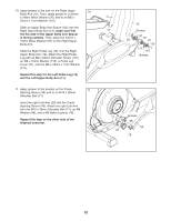
4. Identify the Left Crank Arm (36), which is 4 marked with an "L" sticker. Hold the Left Crank Arm against the left Crank Hub (38), and align the holes in the Left Crank Arm with the unused holes in the Crank Hub. Next, insert four Hub 98 123 Screws (87) into the Left Crank Arm, and finger tighten the Hub Screws into the Crank Hub. 38 Tighten one of the Hub Screws, and then tight- en the Hub Screw farthest from the first Hub Screw. Then, tighten the remaining two Hub Screws. 87 75 116 Attach a Hub Cover (75) to the Left Crank Arm (36) with four M8 x 15mm Button Screws (116). Repeat this step on the other side of the elliptical exerciser. Make sure that the Crank Arms (36, 123) are oriented as shown. Note: there are no Pulley Screws (98) on the right side. 87 36 116 Cutout 5. While another person holds the Upright (3), 5 connect the Upper Wire Harness (48) to the Lower Wire Harness (49). Gently pull the upper end of the Upper Wire Harness to remove any slack, and insert the Upright into the Base (1). Attach the Upright with an M8 x 69mm Button Bolt (80), an M8 Split Washer (90), and a Bright M8 Nylon Locknut (79). Make sure that the Nylon Locknut is in the hexag- onal hole in the Base. Next, tighten two M8 x 23mm Button Screws (84) and two M8 Split Washers (90) into the Base (1). 3 48 49 79 84 90 1 80 90 90 84 7
-
 1
1 -
 2
2 -
 3
3 -
 4
4 -
 5
5 -
 6
6 -
 7
7 -
 8
8 -
 9
9 -
 10
10 -
 11
11 -
 12
12 -
13
-
14
-
15
-
16
-
17
-
18
-
19
-
20
-
21
-
22
-
23
-
24
-
25
-
26
-
27
-
28
 |
 |