RCA RS2302 User Guide - Page 5
RCA RS2302 - Neo-5 CD Shelf System Manual
 |
UPC - 044319203264
View all RCA RS2302 manuals
Add to My Manuals
Save this manual to your list of manuals |
Page 5 highlights
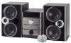
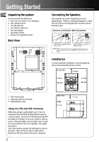
Getting Started EN Unpacking the system: You should have the following: • one main unit (with 2 main speakers); • one remote control; • one FM antenna; • one AM loop antenna; • one user's guide; • one safety leaflet. • Owner and registration Card Connecting the Speakers Each speaker has a black (negative) and a red (positive) jack. When connecting the speakers, match the red wires to the red jacks and the black wires to the black jacks. Antenna and Speaker Wire Connection Back View Push terminal tab down to insert wire. Release tab to lock wire in the terminal. NOTE: Make sure the insulation is completely removed from the ends of the Antenna and speaker wires at all connection points. MAIN SPEAKERS 6 Ω 1 FM GND ANTENNA 2 AM LOOP R L _ 3 + Installation To ensure sufficient ventilation, keep the spacings shown below free from other surfaces: AC 120V/60Hz Front View 4 inches 4 inches VOLUME DEMO/DIMMER ON/STANDBY SOURCE TUNE/PRESET 4 inches RECORD EQ X-BASS CLOCK TIMER SLEEP SHUFFLE REPEAT INTRO CD INFO PROG/SET ST/MONO BAND DISC 1 DISC 2 DISC 3 DISC 4 DISC 5 CD-R / RW COMPATIBLE 5 DISC CHANGER 1. FM Antenna Jack 2. AM Loop antenna connector. 3. Main Speaker Jacks Side View 4 inches 2 inches Using the FM and AM Antennas Before you use your audio system, you'll want to make sure both the FM and AM antennas are positioned properly. Connect the FM antenna to the FM connector on the back of the unit. Uncoil it, making sure it is fully extended. (you may even want to tape it to the wall behind the unit if possible. The higher the better.) You'll also need to connect the AM antenna loop to the back of the unit if you listen to AM stations. Rotate the AM loop antenna for better reception. 2
-
 1
1 -
 2
2 -
 3
3 -
 4
4 -
 5
5 -
 6
6 -
 7
7 -
 8
8 -
 9
9 -
 10
10 -
 11
11 -
12
-
13
-
14
-
15
-
16
-
17
-
18
-
19
-
20
 |
 |
