Ryobi BS904 Operation Manual - Page 10
Mounting The Saw Table, Squaring The Saw Table To The Blade, Adjusting Blade Tension, Tracking - switch key
 |
View all Ryobi BS904 manuals
Add to My Manuals
Save this manual to your list of manuals |
Page 10 highlights
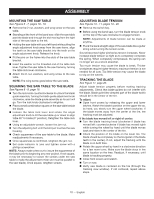
ASSEMBLY MOUNTING THE SAW TABLE See Figures 6 - 7, pages 18 - 19. Remove the D-nut, washers, and wing screw on the saw table. Standing at the front of the band saw, slide the saw table past the blade and through the slot moving from the right side of the saw table to the left. Holding the saw table with your left hand while pulling the angle adjustment knob away from the saw frame, align the teeth on the saw table bracket into the teeth on the angle adjustment knob. Release the knob. Fit the pins on the frame into the slots of the saw table bracket. Insert the washer on the threaded end of the table lock lever. Tighten the saw table to the saw frame by turning the table lock lever clockwise. Attach the D-nut, washers, and wing screw to the saw table. NOTE: The wing screw goes below the saw table. SQUARING THE SAW TABLE TO THE BLADE See Figures 8 - 9, page 19. Turn the lock knob counterclockwise to unlock the blade guide assembly. Turning the blade guide adjustment knob clockwise, raise the blade guide assembly as far as it will go. Turn the lock knob clockwise to retighten. Place a small combination square on the saw table beside the blade. Loosen the table lock lever and rotate the angle adjustment knob to tilt the saw table up or down to align table 90° to blade (0° position). Retighten the table lock lever. Using an adjustable wrench, loosen the jam nut. Turn the adjusting bolt until the bolt just touches the saw housing. Check squareness of the saw table to the blade. Make readjustments if necessary. Once squareness is confirmed, retighten the jam nut. Set scale indicator to zero and tighten screw with a phillips screwdriver. NOTE: Always make a test cut to insure the squareness of the blade prior to beginning any new project. If not square, it may be necessary to loosen the screws under the saw table to make the adjustment (miter slot must be parallel to the saw blade). Once square, retighten screws. ADJUSTING BLADE TENSION See Figures 10 - 11, pages 19 - 20. Remove the switch key. Before using the band saw, turn the blade tension knob on the top of the saw clockwise to engage tension. NOTE: Adjustments of blade tension can be made at anytime. Pluck the back straight edge of the saw blade like a guitar string while turning the tension knob. Sound becomes higher pitched as tension increases. Never increase blade tension so tight as to completely compress the spring. When completely compressed, the spring can no longer act as a shock absorber. Too much tension may cause the blade to break. Thicker workpieces require higher tension; maximum tension is not needed for all cuts. Too little tension may cause the blade to slip on the wheels. TRACKING THE BLADE See Figure 11, page 20. Adjust blade tension properly before making tracking adjustments. Check that blade guides do not interfer with the blade. Blade gullet (the deepest part of the blade tooth) should be in the center of the tire. To adjust: Open front covers by releasing the upper and lower latches. Watch the blade's position on the upper tire as, by hand, you slowly turn the upper wheel clockwise. If the blade moves away from the center of the tire, the tracking must be adjusted. If the blade has moved left or right of center: Turn the blade tracking knob (clockwise if blade has moved left; counterclockwise if blade has moved right) while turning the wheel by hand until the blade moves back and rides in the center of the tire. Check the position of the blade on the lower tire. The blade should be completely on the tire (gullet of the blade teeth in the center). If not, adjust the tracking until the blade is on both tires. Rotate the upper wheel by hand in a clockwise direction for a few more turns. Make sure the blade stays in the same location on the tires. Readjust, if necessary, until blade is tracking properly. Close front covers and relatch. Turn on saw. Verify saw blade is centered on the tire (through the tracking view window). If not centered, repeat above steps. 10 - English
-
 1
1 -
2
-
3
-
4
-
 5
5 -
 6
6 -
 7
7 -
 8
8 -
 9
9 -
 10
10 -
 11
11 -
 12
12 -
 13
13 -
 14
14 -
 15
15 -
16
-
17
-
18
-
19
-
20
-
21
-
22
-
23
-
24
-
25
-
26
-
27
-
28
-
29
-
30
-
31
-
32
-
33
-
34
-
35
-
36
-
37
-
38
-
39
-
40
-
41
-
42
-
43
-
44
-
45
-
46
-
47
-
48
-
49
-
50
-
51
-
52
-
53
-
54
-
55
-
56
 |
 |
