Ryobi BS904 Operation Manual - Page 14
Adjustments
 |
View all Ryobi BS904 manuals
Add to My Manuals
Save this manual to your list of manuals |
Page 14 highlights
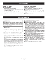
ADJUSTMENTS ADJUSTING BLADE GUIDE ASSEMBLY See Figures 17 - 18, page 21. To prevent the blade from twisting or breaking, the blade guide assembly should always be set approximately 1/8 in. above the workpiece. Turn the lock knob counterclockwise to unlock the blade guide assembly. As a guide, use a scrap piece of the same wood you are about to cut to set the height of the blade guide assembly. Adjust the blade guide assembly by turning the blade guide knob. Lock blade guide assembly in place by turning the lock knob clockwise. Always lock the blade guide assembly in place before turning on the band saw. ADJUSTING BLADE GUIDE SUPPORT AND THRUST BEARINGS See Figure 19, page 22. NOTE: Tighten the lock knob and refer to Adjusting Blade Tension and Tracking the Blade procedures explained in the ASSEMBLY section of this operator's manual prior to making adjustments. The upper and lower blade thrust bearings support and bearing guides the saw blade during cutting operations. The adjustment of the bearings and guides should be checked whenever a different blade is installed. To Adjust Thrust Bearings: The thrust bearings support the back edge of the blade during cutting. The blade should not contact the thrust bearings when you stop cutting. It is important that both upper and lower thrust bearings be adjusted equally. Open the front covers and blade guard. Using a hex key, loosen the upper and lower thrust bearing screws and push thrust bearings to the back of the saw. Verify that saw blade is tracking correctly, then slide the thrust bearing forward until the bearing is within 1/64 in. of the blade. Tighten the thrust bearing screw securely. Slide lower bearing forward until it has proper clearance. Tighten the thrust bearing screw securely. To Adjust Blade Guide Support: Loosen the blade guide support and blade guide set screws using hex keys. Slide the upper blade guide support on the shaft until the front edge of the guides contact the saw blade behind the gullet. Tighten the screw securely. Push the right guide to contact the blade and release. Slowly rotate wheel one full rotation. Tighten blade guide set screws. Adjust left side guide to allow 1/64 in. clearance between the blade and guide (about the thickness of a dollar bill) by inserting dollar bill between left guide and blade. Apply pressure to left guide pin to hold dollar bill in place. Tighten set screw and remove dollar bill. Rotate, by hand, a full three rotations to make sure blade will not bind. Close the blade guard and front cover. Relatch. Repeat this procedure for the lower blade guide support. 14 - English
-
 1
1 -
2
-
3
-
4
-
5
-
6
-
7
-
8
-
 9
9 -
 10
10 -
 11
11 -
 12
12 -
 13
13 -
 14
14 -
 15
15 -
 16
16 -
 17
17 -
 18
18 -
 19
19 -
20
-
21
-
22
-
23
-
24
-
25
-
26
-
27
-
28
-
29
-
30
-
31
-
32
-
33
-
34
-
35
-
36
-
37
-
38
-
39
-
40
-
41
-
42
-
43
-
44
-
45
-
46
-
47
-
48
-
49
-
50
-
51
-
52
-
53
-
54
-
55
-
56
 |
 |