Ryobi TS1355LA English Manual - Page 12
Features, Tools Needed - compound miter saw
 |
View all Ryobi TS1355LA manuals
Add to My Manuals
Save this manual to your list of manuals |
Page 12 highlights
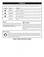
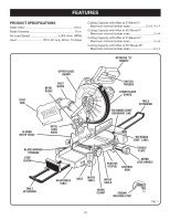
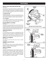
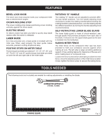
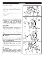
FEATURES BEVEL LOCK KNOB The bevel lock knob securely locks your compound miter saw at desired bevel angles. CROWN MOLDING STOP The crown molding stop makes positioning crown molding vertically against the fence easier. ELECTRIC BRAKE An electric brake has been provided to quickly stop blade rotation after the switch is released. LASER GUIDE For more accurate cuts, a laser guide is included with the miter saw. When used properly, the laser guide makes accurate, precision cutting simple and easy. POSITIVE STOPS ON MITER TABLE Positive stops have been provided at 0°, 15°, 22-1/2°, 30°, and 45°. The 22-1/2° and 45° positive stops have been provided on both the left and right side of the miter table. ROTATING "D" HANDLE The rotating "D" handle can be adjusted to provide different saw handle positions. Turn the handle adjusting knob clockwise to loosen the rotating handle before twisting the rotating handle to a desired position. Lock the rotating handle into different positions by turning the handle adjusting knob counterclockwise. SELF-RETRACTING LOWER BLADE GUARD The lower blade guard is made of shock-resistant, seethrough plastic that provides protection from each side of the blade. It retracts over the upper blade guard as the saw is lowered into the workpiece. SLIDING MITER FENCE The miter fence on the compound miter saw has been provided to hold your workpiece securely against when making all cuts. The left side is larger providing additional support. It has a sliding feature for clearance of the saw arm when making bevel or compound cuts. Loosen the fence screw before attempting to slide the miter fence. Once the desired position of the miter fence is determined, tighten the fence screw to secure the sliding fence. TOOLS NEEDED The following tools (not included) are needed for making adjustments or installing the blade: COMBINATION WRENCH (2) (10 mm, 12 mm) FRAMING SQUARE 12 COMBINATION SQUARE Fig. 5
-
 1
1 -
2
-
3
-
4
-
5
-
6
-
 7
7 -
 8
8 -
 9
9 -
 10
10 -
 11
11 -
 12
12 -
 13
13 -
 14
14 -
 15
15 -
 16
16 -
 17
17 -
18
-
19
-
20
-
21
-
22
-
23
-
24
-
25
-
26
-
27
-
28
-
29
-
30
-
31
-
32
-
33
-
34
 |
 |