Ryobi TS1355LA English Manual - Page 30
Adjustments
 |
View all Ryobi TS1355LA manuals
Add to My Manuals
Save this manual to your list of manuals |
Page 30 highlights
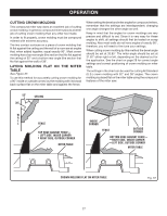
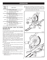
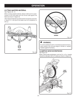
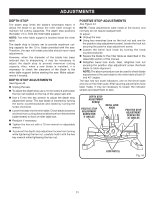
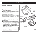
ADJUSTMENTS WARNING: Before performing any adjustment, make sure the tool is unplugged from the power supply. Failure to heed this warning could result in serious personal injury. The compound miter saw has been adjusted at the factory for making very accurate cuts. However, some of the components might have been jarred out of alignment during shipping. Also, over a period of time, readjustment will probably become necessary due to wear. After unpacking the saw, check the following adjustments before you begin using saw. Make any readjustments that are necessary and periodically check the parts alignment to make sure that the saw is cutting accurately. CAUTION: Do not start the compound miter saw without checking for interference between the blade and the throat plate. Damage could result to the blade if it strikes the throat plate during operation of the saw. PIVOT ADJUSTMENTS NOTE: These adjustments were made at the factory and normally do not require readjustment. TRAVEL PIVOT ADJUSTMENT The saw arm should rise completely to the up position by itself. If the saw arm does not raise by itself or if there is play in the pivot joints, have saw repaired at your nearest RYOBI AUTHORIZED SERVICE CENTER. BEVEL PIVOT ADJUSTMENT The compound miter saw should bevel easily by loosening the bevel lock knob and tilting the saw arm to the left. If movement is tight or if there is play in the pivot, have saw repaired at your nearest RYOBI AUTHORIZED SERVICE CENTER. TO ADJUST THE LASER GUIDE See Figure 43. NOTE: Avoid direct eye exposure when using the laser guide. Set both the bevel angle and the miter table at 0°. Use the work clamp or a C-clamp to secure a piece of scrap wood. Plug the saw into the power source and make a slight cut to score the wood. Release the switch trigger and allow the saw blade to stop rotating before raising the blade. Raise the saw arm and unplug the saw. Loosen the blade bolt cover screw on the blade bolt cover until the cover can be raised. Gently raise the lower blade guard bracket so that lower blade guard and blade bolt cover can be rotated up and back to expose the laser. Rotate the blade by hand until you can push and hold the laser button and the laser is near the center of the workpiece as shown in figure 43. To adjust the laser, turn the adjustment screw counterclockwise or clockwise using the hex key (1/16 in.) provided. NOTE: When properly aligned, the laser should be on the left edge of the kerf. Once aligned, remove and store the hex key (1/16 in.). Replace the lower blade guard and blade bolt cover. Retighten the blade bolt cover screw securely to prevent guard movement (see page 17, figure 17). NOTE: Always make practice cuts on scrap wood before cutting through your workpiece. ADJUSTMENT SCREW mn mn LASER APERTURE BUTTON LASER MARK 30 HEX KEY Fig. 43
-
 1
1 -
2
-
3
-
4
-
5
-
6
-
7
-
8
-
9
-
10
-
11
-
12
-
13
-
14
-
15
-
16
-
17
-
18
-
19
-
20
-
21
-
22
-
23
-
24
-
 25
25 -
 26
26 -
 27
27 -
 28
28 -
 29
29 -
 30
30 -
 31
31 -
 32
32 -
 33
33 -
 34
34
 |
 |