Samsung HLR6768W User Manual (ENGLISH) - Page 14
Rear Panel Jacks, DVI INPUT jack HDMI IN 2/DVI - settings
 |
View all Samsung HLR6768W manuals
Add to My Manuals
Save this manual to your list of manuals |
Page 14 highlights
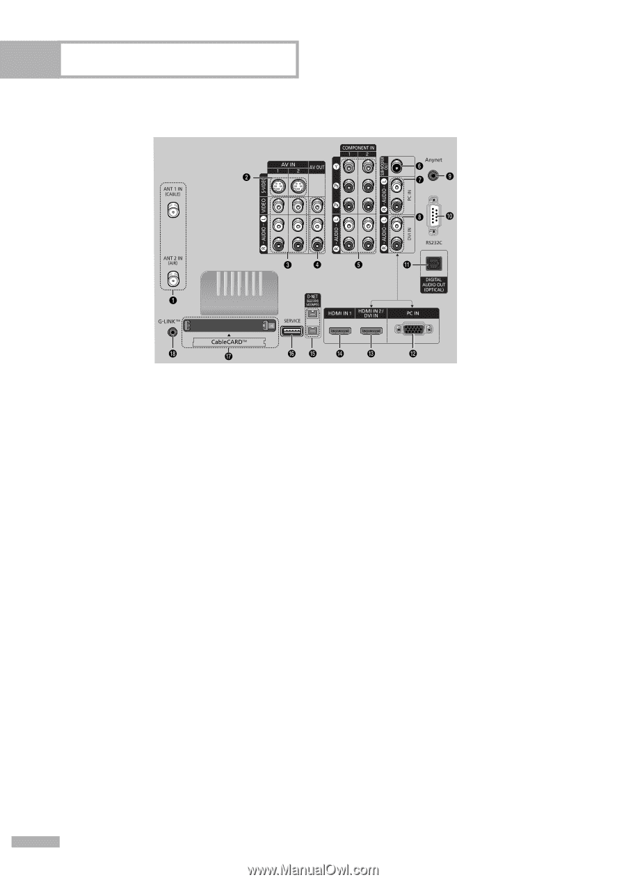
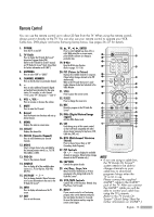
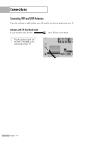
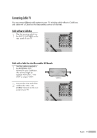
Your New Wide TV Rear Panel Jacks Œ ANTENNA terminals Two independent cables or antennas can be connected to these terminals. Use "ANT 1 IN (CABLE)" and "ANT 2 IN (AIR)" terminals to receive a signal from VHF/UHF antennas or your cable system. (Refer to pages 18~19) ´ S-VIDEO INPUT jacks Connects an S-Video signal from an S-VHS VCR or DVD player. (Refer to pages 20 and 22) ˇ VIDEO/AUDIO INPUT jacks Connect video/audio signals from external sources, such as VCR or DVD players. (Refer to page 23) ¨ VIDEO/AUDIO OUTPUT jacks Sends video/audio signals from the TV to an external source, such as a VCR. These jacks are available only in RF, Video and S-Video modes. ˆ COMPONENT1, 2 jacks (Y, PB, PR, AUDIO L/R) Use these jacks to connect the component video/audio signals from a DVD player or a Set-Top Box. (Refer to pages 23~24) Ø SUB-WOOFER OUT jack Connect to an active SUB-WOOFER. (Refer to page 27) ∏ PC AUDIO INPUT jacks Connect these to the audio output jacks on your PC. (Refer to page 128) " HDMI 2/DVI IN (AUDIO L/R) Connect to the DVI audio output jack of an external device. ' Anynet This jack is for connecting to other Samsung Anynet-enabled devices. Please refer to the Anynet Owner's Instruction. ˝ RS232C Connect to a computer for reading and loading data information. Ô DIGITAL AUDIO OUT (OPTICAL) jack Connect to a Digital Audio Component. (Refer to page 26) PC VIDEO INPUT jack Connect these to the video output jack on your PC. Ò HDMI (High Definition Multimedia Interface)/ DVI INPUT jack (HDMI IN 2/DVI IN) Connect to the HDMI jack of a device with HDMI output. These inputs can also be used as a DVI connection with separate analog audio inputs. An optional HDMI/DVI cable will be necessary to make this connection. When using the optional HDMI/DVI adapter, the DVI analog audio inputs on your TV allow you to receive left and right audio from your DVI device. (Not compatible with PC) (Refer to pages 24~25) Ú HDMI (High Definition Multimedia Interface) INPUT jacks (HDMI IN 1) Connect to the HDMI jack of a device with HDMI output. (Not compatible with PC) Æ D-Net (IEEE1394) S400 MPEG Connect to external IEEE1394 digital products such as digital VCRs and camcorders. Two jacks are provided for this purpose, which allow for a high degree of flexibility for connecting your D-Net controlled system. (Refer to pages 112~126) ı SERVICE This jack is for software upgrades. ˜ CableCARDTM Insert the CableCARD into the slot. (Refer to page 21) ¯ G-LINKTM Connect the IR controller cable to the G-LINKTM terminal on your TV. (Refer to page 104) English - 14
-
 1
1 -
2
-
3
-
4
-
5
-
6
-
7
-
8
-
 9
9 -
 10
10 -
 11
11 -
 12
12 -
 13
13 -
 14
14 -
 15
15 -
 16
16 -
 17
17 -
 18
18 -
 19
19 -
20
-
21
-
22
-
23
-
24
-
25
-
26
-
27
-
28
-
29
-
30
-
31
-
32
-
33
-
34
-
35
-
36
-
37
-
38
-
39
-
40
-
41
-
42
-
43
-
44
-
45
-
46
-
47
-
48
-
49
-
50
-
51
-
52
-
53
-
54
-
55
-
56
-
57
-
58
-
59
-
60
-
61
-
62
-
63
-
64
-
65
-
66
-
67
-
68
-
69
-
70
-
71
-
72
-
73
-
74
-
75
-
76
-
77
-
78
-
79
-
80
-
81
-
82
-
83
-
84
-
85
-
86
-
87
-
88
-
89
-
90
-
91
-
92
-
93
-
94
-
95
-
96
-
97
-
98
-
99
-
100
-
101
-
102
-
103
-
104
-
105
-
106
-
107
-
108
-
109
-
110
-
111
-
112
-
113
-
114
-
115
-
116
-
117
-
118
-
119
-
120
-
121
-
122
-
123
-
124
-
125
-
126
-
127
-
128
-
129
-
130
-
131
-
132
-
133
-
134
-
135
-
136
-
137
-
138
-
139
-
140
-
141
-
142
-
143
-
144
 |
 |