Samsung TX-P2664W User Manual (user Manual) (ver.1.0) (English) - Page 18
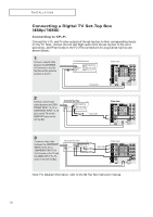
Connecting a Digital TV Set-Top Box (480p/1080i), Connecting to Y, P
 |
View all Samsung TX-P2664W manuals
Add to My Manuals
Save this manual to your list of manuals |
Page 18 highlights
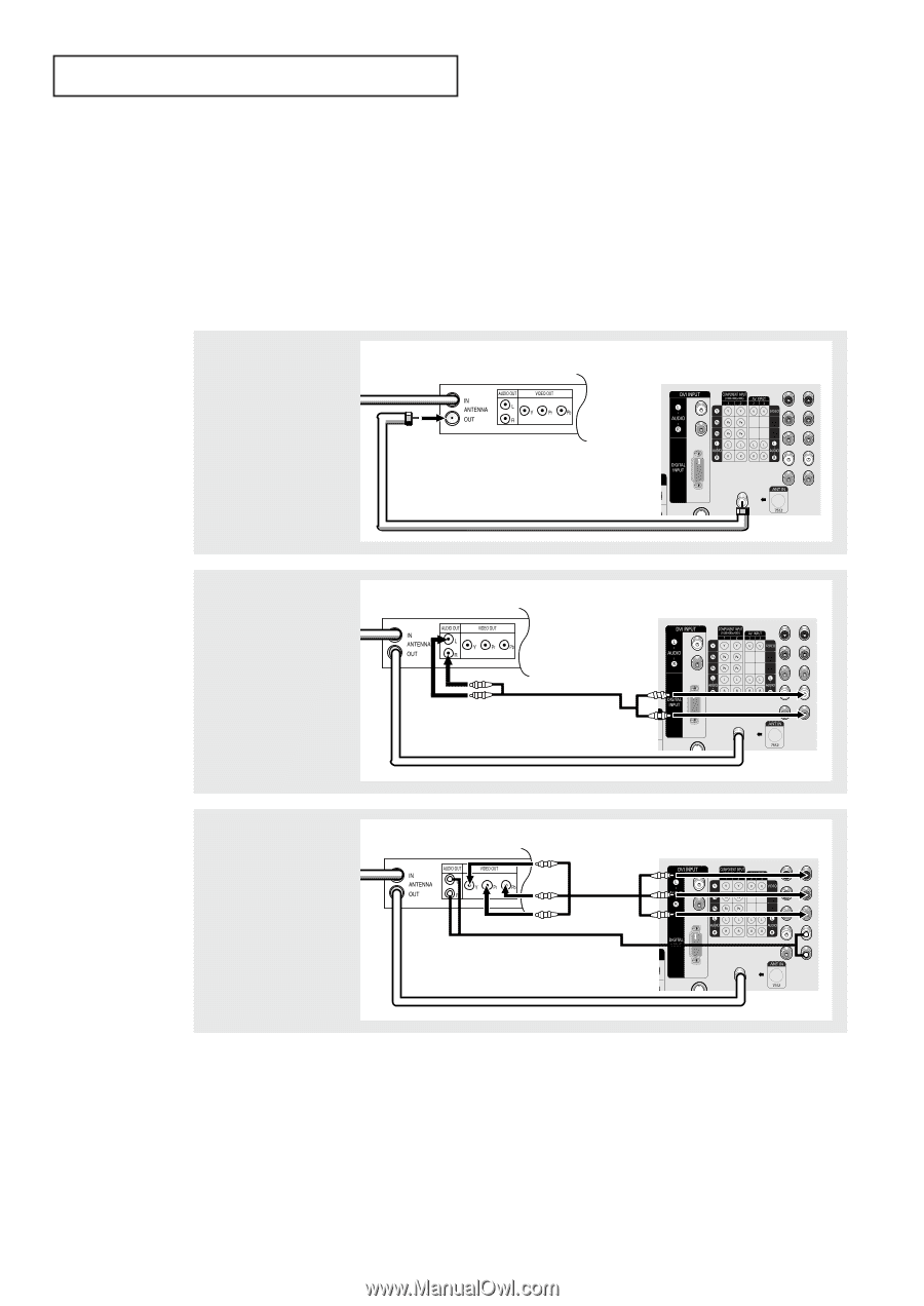
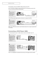
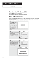
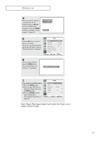
INSTALLATION Connecting a Digital TV Set-Top Box (480p/1080i) Connecting to Y,PB,PR Connect the Y, PB, and PR video outputs of the set-top box to their corresponding inputs on the TV. Next, connect the Left and Right audio from the set-top box to the corresponding L and R terminals on the TV. (The connections for a typical set-top box are shown below.) 1 Connect a coaxial cable between the ANTENNA OUT terminal on the Set Top Box and the antenna terminal on the TV. Set Top Box Rear Panel TV Rear Panel Coaxial Cable 2 Connect a set of audio cables between the COMPONENT INPUT 2 (L, R) or COMPONENT INPUT 1 (L, R) jacks on the TV and the AUDIO OUT jacks on the Set Top Box. Set Top Box Rear Panel Audio Cable TV Rear Panel 3 Connect a video cable between the COMPONENT INPUT 2 (Y, PB, PR) or COMPONENT INPUT 1 (Y, PB, PR) jacks on the TV and the VIDEO OUT (Y, PB, PR) jacks on the Set Top Box. Set Top Box Rear Panel Video Cable TV Rear Panel Note: For detailed information, refer to the Set Top Box instruction manual. 18
-
 1
1 -
2
-
3
-
4
-
5
-
6
-
7
-
8
-
9
-
10
-
11
-
12
-
 13
13 -
 14
14 -
 15
15 -
 16
16 -
 17
17 -
 18
18 -
 19
19 -
 20
20 -
 21
21 -
 22
22 -
 23
23 -
24
-
25
-
26
-
27
-
28
-
29
-
30
-
31
-
32
-
33
-
34
-
35
-
36
-
37
-
38
-
39
-
40
-
41
-
42
-
43
-
44
-
45
-
46
-
47
-
48
-
49
-
50
-
51
-
52
-
53
-
54
-
55
-
56
-
57
-
58
-
59
-
60
-
61
-
62
-
63
-
64
-
65
-
66
-
67
-
68
 |
 |