Sanyo DP26648 Service Manual - Page 36
Supply Voltage, Input, Delay Capacitor, Output
 |
View all Sanyo DP26648 manuals
Add to My Manuals
Save this manual to your list of manuals |
Page 36 highlights
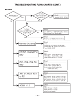
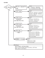
IC6200, Audio DAC 1.5V to 3.3V Hardware Control Reset Serial Audio Input Level Translator 3.3 V Hardware Configuration PCM Serial Interface Interpolation Filter Multibit ∆∑Modulator Interpolation Filter Multibit ∆∑Modulator Auto Speed Mode Detect 9 V to 12 V DAC Amp + Filter 2 Vrms Line Level Left Channel Output DAC Amp + Filter 2 Vrms Line Level Right Channel Output Internal Voltage Reference External Mute Control Left and Right Mute Controls 5900, Voltage detecting delay circuit BLOCK DIAGRAM N.C. SUPPLY VOLTAGE 8 7 N.C. 1 5μA INPUT 2 1.25V 3 4 5 N.C. GND DELAY CAPACITOR 6 OUTPUT - 36 -
-
 1
1 -
2
-
3
-
4
-
5
-
6
-
7
-
8
-
9
-
10
-
11
-
12
-
13
-
14
-
15
-
16
-
17
-
18
-
19
-
20
-
21
-
22
-
23
-
24
-
25
-
26
-
27
-
28
-
29
-
30
-
 31
31 -
 32
32 -
 33
33 -
 34
34 -
 35
35 -
 36
36 -
 37
37 -
 38
38 -
 39
39 -
 40
40 -
 41
41 -
42
-
43
-
44
-
45
-
46
-
47
-
48
-
49
-
50
-
51
-
52
-
53
-
54
-
55
-
56
-
57
 |
 |

— 36 —
1.5V to 3.3V
3.3 V
9 V to 12 V
2 Vrms Line Level
Left Channel
Output
2 Vrms Line Level
Right Channel
Output
Left and Right
Mute Controls
Hardware Control
Level Translator
Hardware
Configuration
PCM
Serial
Interface
Auto Speed
Mode Detect
Internal Voltage
Reference
External
Mute
Control
Interpolation
Filter
Multibit
∆∑
Modulator
DAC
DAC
Multibit
∆∑
Modulator
Amp
+
Filter
Amp
+
Filter
Interpolation
Filter
Reset
Serial Audio Input
IC6200, Audio DAC
1
2
3
4
5
6
8
7
SUPPLY VOLTAGE
5μA
1.25V
N.C.
N.C.
INPUT
N.C.
GND
DELAY CAPACITOR
OUTPUT
5900,Voltage detecting delay circuit