Sanyo DP26648 Service Manual - Page 5
Power Failure Circuit - inverter board
 |
View all Sanyo DP26648 manuals
Add to My Manuals
Save this manual to your list of manuals |
Page 5 highlights
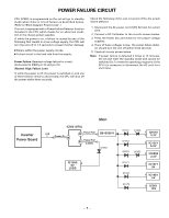
POWER FAILURE CIRCUIT CPU (IC800) is programmed so the set will go to standby mode when there is circuit failure as described below. (Refer to"Block Diagram Power Lines".) This unit is equipped with a Power Failure Detector function included in the CPU which checks for an abnormal condition in the chassis power supplies. If, while the power is on, a failure is caused by any of the following that results in a low voltage supply, the CPU will turn the unit off in 1.5 seconds to prevent further damage: • Failure within the power supply circuits. • A short circuit in the load side from the supply. Power Failure: Detected voltage failure for circuit. (Connected to IC800 pin 32 and pin 23.) (Normal: High; Failure: Low) If, while the power is off, the power is switched on and any of these failures remains uncorrected, the CPU will shut off the power within three seconds. Check the following if the unit is turned off by the power failure detector. 1. Disconnect the AC power cord (120V AC line) for a short time. 2. Connect a DC Voltmeter to the circuits shown below. 3. Press the Power key and check for the proper voltage supplies. 4. If any of these voltages is low, the power failure detec- tor should turn the unit off within three seconds. 5. Check all circuits shown below. Note: If power failure is detected 3 times in 15 minutes, the set will enter the standby mode and cannot be switched On.To reset the operating programs of the CPU it is necessary to disconnect the AC cord for a short time. Inverter Power Board Main IC800 (CPU) K8B 1 Power On 18 32 Power Fail Q810/Q811 23 Power Fail (LVDS) D1683 IC1680 2 5V LVDS D1621 D1653 D6053 D1620 5 Q1610 6 3.3V 8 IC1651 6.5V D6052 6 IC6050 3.3V D1671 5 IC1671 9V D1662 6 IC1661 5V D1679 9 IC001 10V -5-
-
 1
1 -
 2
2 -
 3
3 -
 4
4 -
 5
5 -
 6
6 -
 7
7 -
 8
8 -
 9
9 -
 10
10 -
 11
11 -
12
-
13
-
14
-
15
-
16
-
17
-
18
-
19
-
20
-
21
-
22
-
23
-
24
-
25
-
26
-
27
-
28
-
29
-
30
-
31
-
32
-
33
-
34
-
35
-
36
-
37
-
38
-
39
-
40
-
41
-
42
-
43
-
44
-
45
-
46
-
47
-
48
-
49
-
50
-
51
-
52
-
53
-
54
-
55
-
56
-
57
 |
 |
