Seagate ST340015A Product Manual - Page 32
Barracuda 5400.1 Product Manual, Rev. F, Ultra ATA/100 cable, Note., Drive mounting
 |
View all Seagate ST340015A manuals
Add to My Manuals
Save this manual to your list of manuals |
Page 32 highlights
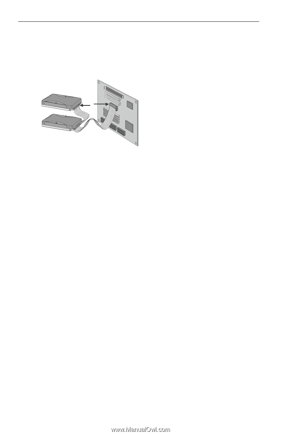
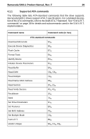
24 Barracuda 5400.1 Product Manual, Rev. F 3.3.3 Ultra ATA/100 cable An 80-conductor 40-pin cable is required to run Ultra DMA mode 3, mode 4 and mode 5. This cable uses even-numbered conductors connected to the ground pins to improve signal integrity. Master Slave Pin 1 Note. If you are using a 40-pin 80-conductor cable, attach the blue connector to the motherboard, the black connector to the MCoothmeprbuotearrd master drive, and the grey connector to the slave. Figure 5. Ultra ATA cable connectors Note. The drive supports both host and drive cable detection. The host detects the 80-conductor cable by sampling pin 34, CBLID-, on the interface bus. The drive detects the 80-conductor cable by sensing a capacitor at the host side through the CBLID- signal. The result is reported in a Fast Rise Detected bit (bit 13 of word 93 in the Identify drive parameter block). 3.4 Drive mounting You can mount the drive in any orientation using four screws in the sidemounting holes or four screws in the bottom-mounting holes. See Figure 6 for drive mounting dimensions. Follow these important mounting precautions when mounting the drive: • Allow a minimum clearance of 0.030 inches (0.76 mm) around the entire perimeter of the drive for cooling. • Use only 6-32 UNC mounting screws. • Use only .045" +/- .005 high by .050" diameter bosses (4x) for bottom mounting applications to prevent deformation of the SeaShield. • Do not overtighten the mounting screws (maximum torque: 6 inch-lb). • Do not use a drive interface cable that is more than 18 inches long.
-
 1
1 -
2
-
3
-
4
-
5
-
6
-
7
-
8
-
9
-
10
-
11
-
12
-
13
-
14
-
15
-
16
-
17
-
18
-
19
-
20
-
21
-
22
-
23
-
24
-
25
-
26
-
 27
27 -
 28
28 -
 29
29 -
 30
30 -
 31
31 -
 32
32 -
 33
33 -
 34
34 -
 35
35 -
 36
36 -
 37
37 -
38
-
39
-
40
-
41
-
42
-
43
-
44
-
45
-
46
-
47
-
48
-
49
-
50
-
51
-
52
-
53
-
54
-
55
-
56
-
57
-
58
 |
 |