Seagate ST340015A Product Manual - Page 35
ATA interface
 |
View all Seagate ST340015A manuals
Add to My Manuals
Save this manual to your list of manuals |
Page 35 highlights
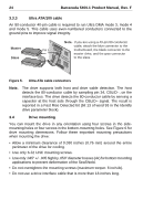
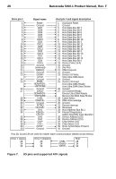
Barracuda 5400.1 Product Manual, Rev. F 27 4.0 ATA interface These drives use the industry-standard ATA task file interface that supports 16-bit data transfers. It supports ATA programmed input/output (PIO) modes 0-4; multiword DMA modes 0-2, and Ultra DMA modes 0-5. The drive also supports the use of the IORDY signal to provide reliable high-speed data transfers. You can use a daisy-chain cable to connect two drives to a single AT host bus. For detailed information about the ATA interface, refer to the draft of AT Attachment with Packet Interface Extension (ATA/ATAPI-7), NCITS T13, subsequently referred to as the Draft ATA-7 Standard. 4.1 ATA interface signals and connector pins Figure 7 on page 28 summarizes the signals on the ATA interface connector that the drive supports. For a detailed description of these signals, refer to the Draft ATA-7 Standard.
-
 1
1 -
2
-
3
-
4
-
5
-
6
-
7
-
8
-
9
-
10
-
11
-
12
-
13
-
14
-
15
-
16
-
17
-
18
-
19
-
20
-
21
-
22
-
23
-
24
-
25
-
26
-
27
-
28
-
29
-
 30
30 -
 31
31 -
 32
32 -
 33
33 -
 34
34 -
 35
35 -
 36
36 -
 37
37 -
 38
38 -
 39
39 -
 40
40 -
41
-
42
-
43
-
44
-
45
-
46
-
47
-
48
-
49
-
50
-
51
-
52
-
53
-
54
-
55
-
56
-
57
-
58
 |
 |
