Seagate ST340015A Product Manual - Page 7
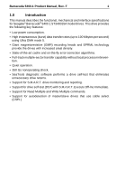
List of s - ata
 |
View all Seagate ST340015A manuals
Add to My Manuals
Save this manual to your list of manuals |
Page 7 highlights
Barracuda 5400.1 Product Manual, Rev. F v List of Figures Figure 1. Figure 2. Figure 3. Figure 4. Figure 5. Figure 6. Figure 7. Typical 5V startup and operation current profile 11 Typical 12V startup and operation current profile 11 Breather filter hole location 22 Master/slave jumper settings 23 Ultra ATA cable connectors 24 Mounting dimensions-top, side and end view 25 I/O pins and supported ATA signals 28
-
 1
1 -
 2
2 -
 3
3 -
 4
4 -
 5
5 -
 6
6 -
 7
7 -
 8
8 -
 9
9 -
 10
10 -
 11
11 -
 12
12 -
13
-
14
-
15
-
16
-
17
-
18
-
19
-
20
-
21
-
22
-
23
-
24
-
25
-
26
-
27
-
28
-
29
-
30
-
31
-
32
-
33
-
34
-
35
-
36
-
37
-
38
-
39
-
40
-
41
-
42
-
43
-
44
-
45
-
46
-
47
-
48
-
49
-
50
-
51
-
52
-
53
-
54
-
55
-
56
-
57
-
58
 |
 |

Barracuda 5400.1 Product Manual, Rev. F
v
List of Figures
Figure 1.
Typical 5V startup and operation current profile . . . . . . . . . 11
Figure 2.
Typical 12V startup and operation current profile . . . . . . . . 11
Figure 3.
Breather filter hole location . . . . . . . . . . . . . . . . . . . . . . . . . 22
Figure 4.
Master/slave jumper settings . . . . . . . . . . . . . . . . . . . . . . . 23
Figure 5.
Ultra ATA cable connectors . . . . . . . . . . . . . . . . . . . . . . . . 24
Figure 6.
Mounting dimensions—top, side and end view. . . . . . . . . . 25
Figure 7.
I/O pins and supported ATA signals . . . . . . . . . . . . . . . . . . 28