Seagate ST3500630A Serial ATA - A Comparison with Ultra ATA Technology (57K, P - Page 5
Serial ATA - Tighter Impedance Specifications / Support for Automatic Impedance Matching - driver
 |
UPC - 000067575145
View all Seagate ST3500630A manuals
Add to My Manuals
Save this manual to your list of manuals |
Page 5 highlights
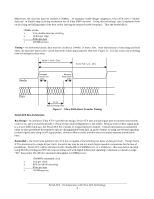
Connectors Ultra ATA - 40-pin dual row header Though the cable has been updated for use in high-speed data transfers, the ATA connector has remained the standard 40-pin dual row header to maintain backward compatibility. The 40 extra ground wires in the cable are tied to the 7 ground pins in the connector. Because additional ground lines have not been added, inductive coupling in the connector introduces a significant amount of crosstalk during switching. The effect of crosstalk is greatest on a signal that remains constant while all neighboring signals transition in the same direction, up to 1V worst case. This generated noise is most problematic when transmitting to the device in the middle of the cable, or when receiving from this device. As crosstalk is proportional to the change in current over time, it can be reduced by limiting the rise and fall times, or slew rate, of the bus drivers. However, this strategy forces lower clock speeds and thus is not conducive to bus speed increases. Serial ATA - 7-pin custom connector The 0.5" wide cable connector directly connects the 4 signal wires and 3 ground lines to the receiving terminal in a single row. Because the connector includes the shielding ground pins, very little crosstalk is introduced. Note that the receiving terminal uses extended connectors for the 3 ground signals so that the ground reference between the device and host can be shared prior to signals being applied at the input. A similar mating sequence is enforced with the new 7/8" wide 15-pin single row power connector. This feature is necessary to accommodate hot-plugging. Termination Strategy Ultra ATA - Source Termination Ultra ATA configurations are source terminated to minimize ringing. Using this termination scheme, a series resistor is placed at the driver's transmit output. The magnitude of this resistance is chosen so that the resistance plus the output impedance of the transmitter match the controlled trace and/or cable impedance. This produces a voltage divider at the output of the driver that effectively halves the strength of the emitted signal. When this signal reaches the receiver, the signal reflects at the impedance mismatch formed between the controlled impedance transmission line or cable and the very high input resistance of the receiver. This reflection doubles the strength of the signal at the receiver, and thus the signal returns to the original amplitude. When the reflected signal propagates back to the source, it sees a continuous impedance path to ground and thus is completely damped assuming perfect termination. If the termination resistor is poorly chosen, some of this reflected signal will be again reflected and will cause ringing in the signal. If the ringing is of great enough amplitude, settling time of the signal may be affected. This termination scheme is very effective when using a single driver and receiver at opposite ends of the connecting cable. The standard ATA cable, however, allows a second device to be attached in the middle of the signal path. At this point in the cable, the signal experiences a "plateau" as the transmitted signal will arrive at half strength and the reflected signal must propagate backwards from the receiver before full voltage swing is achieved. If overshoot of the initial signal is great enough, the half-amplitude signal may cross the switching threshold on or more times before the reflected signal arrives. This overshoot can also be controlled by limiting output slew rate, but as mentioned above this solution will be problematic if greater bus speed is desired. Serial ATA - Tighter Impedance Specifications / Support for Automatic Impedance Matching Since Serial ATA uses only 4 signal lines per channel, proper termination of all lines is less costly, both in design complexity and dollars. All devices are required to provide precision termination impedances. Support is also provided for active impedance matching circuits that ensure exact matching to any cable or device. Though Serial ATA utilizes the same source termination scheme as parallel ATA, many of the problems are reduced by this near-perfect termination and the point-to-point connection topology, which ensures that the only receiver is at the endpoint of the transmission line. PCB Routing Ultra ATA - Parallel Data Bus and Clock Routing Constraints Because the ATA interface uses 32 signal lines for each channel, with a typical configuration of 2 Ultra ATA channels per board 64 signals must be routed from the I/O controller to the ATA connector. To minimize crosstalk and ringing, trace widths and separations must be carefully controlled. Typically a maximum routing length of 8" is specified. All trace lengths are typically required to be within 0.5" from that of the strobe line to minimize clock skew. Serial ATA - Differential Pair Routing Constraints Each Serial ATA channel consists of two differential pairs, a total of 4 transmission lines. Each pair should be routed with the differential lines at constant separation and with equal length. Because of the high signaling speed and limitations Serial ATA : A Comparison with Ultra ATA Technology - 5 -
-
 1
1 -
 2
2 -
 3
3 -
 4
4 -
 5
5 -
 6
6 -
 7
7
 |
 |
