Seagate ST3500630A Serial ATA - A Comparison with Ultra ATA Technology (57K, P - Page 6
Signaling, Connection Methodology, Cable and Connector Specification, Added Features
 |
UPC - 000067575145
View all Seagate ST3500630A manuals
Add to My Manuals
Save this manual to your list of manuals |
Page 6 highlights
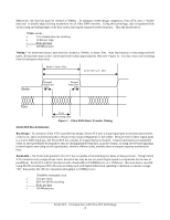
of the common FR4 PCB routing material, trace lengths should typically be less than 6". Though proper routing is more important with Serial ATA than it is with Ultra ATA, there are far fewer signals to route. Each Serial ATA channel requires 4 signal traces, thus support for 4 drives would require a total of 16 routed signals vs. 74 for Ultra ATA. Signaling Ultra ATA - Legacy 5V Tolerance As mentioned above, devices that use Ultra DMA Mode 5, or 100 Mbytes/sec, transmissions must use 3.3V signaling to balance high-to-low and low-to-high transition times. To be fully backward compatible, Ultra ATA devices and hosts must be 5V tolerant to avoid being damaged when connected to ATA/ATAPI-5 or earlier devices. This 5V tolerance must be considered during IC design, as it is expected to become more difficult to support with newer CMOS design processes. Serial ATA - Low Voltage Differential Signaling The noise rejection capabilities of differential pairs allow for low voltage signaling. With Serial ATA, the voltage swing is 0.125V about the common-mode voltage, with a minimumcommon-mode voltage of 0.25V. Because Serial ATA does not maintain hardware compatibility with previous ATA specifications, the 5V tolerance constraint is removed. Serial ATA - Beyond Better Signaling Characteristics... Connection Methodology Ultra ATA - Master/Slave Shared Bus Ultra ATA technology supports up to 2 drives per channel via a shared bus. Though the two attached devices are referred to as "master" and "slave", there is no difference in operation between or priority given to the connected devices. The host bus adapter is the true bus master and uses the master/slave status of the drives to route requests to the correct device and to determine the boot device. Though Ultra ATA supports a command queuing algorithm, it is rarely incorporated into devices, and thus the data bus is locked if a command to either drive is outstanding. Because of this, the bus bandwidth is shared between the master and slave devices when both are actively interacting with the host. Serial ATA - Point to Point Connections for Dedicated Bandwidth Serial ATA uses a point-to-point connection topology, meaning that each source is connected to one destination. Each channel has the capability to work independently so that there is no contention between drives and thus no sharing of interface bandwidth. This connection strategy also negates the need for master/slave jumper settings on devices. Cable and Connector Specification Ultra ATA - Legacy Wide Ribbon Cable Ultra ATA uses a 2" wide 80-wire cable with a maximum specified length of 18". To maintain backward compatibility with prior ATA revisions, Ultra ATA devices use a 40-pin dual-row header connector. This also implies that a 40-pin connector can be plugged in to incompatible Ultra ATA systems. Power is typically supplied by a separate 4-pin power plug. A smaller hardware-incompatible 46-pin version of the cable/connector assembly is available to deliver power and control through a single connector for use with small form factor drives. Serial ATA - Thin, Flexible Cable with Small-Footprint Connector Typical Serial ATA cables are at most 0.25" wide and can be up to 1m in length, allowing for proper routing to minimize restriction to airflow and reduce clutter. The 0.5" wide 7-pin data connector requires little area on board or device, important for upcoming 2.5" hard disk drives. The Serial ATA signal connector and additional power connector are thin enough to be used unmodified on all hard-drive sizes available today, negating the need for multiple connector types. To illustrate the reduced board space requirement, note that in a four drive system, Serial ATA connectors use 25% of the board space required by Ultra ATA. Added Features Ultra ATA - Basic Reliability Support The ATA/ATAPI-6 revision includes support for a CRC error check on data transmissions to ensure that the data sent was received correctly. Control signal transmissions are not protected. Serial ATA : A Comparison with Ultra ATA Technology - 6 -
-
 1
1 -
 2
2 -
 3
3 -
 4
4 -
 5
5 -
 6
6 -
 7
7
 |
 |